AUTOMATIC TRANSAXLE SYSTEM, Diagnostic DTC:P0712, P0713

| DTC Code | DTC Name |
|---|---|
| P0712 | Transmission Fluid Temperature Sensor "A" Circuit Low Input |
| P0713 | Transmission Fluid Temperature Sensor "A" Circuit High Input |
DESCRIPTION
Refer to DTC P0711 Click here.
| DTC Code | DTC Detection Condition | Trouble Area |
|---|---|---|
| P0712 | ATF temperature sensor resistance is less than 79 Ω for 0.5 sec. or more (1-trip detection logic). |
|
| P0713 | ATF temperature sensor resistance is more than 156 kΩ for 0.5 sec. or more when 15 minutes or more have elapsed after the engine starts (1-trip detection logic). |
|
MONITOR DESCRIPTION
These DTCs indicate an open or short in the ATF temperature sensor circuit. The ATF temperature sensor converts ATF temperature into an electrical resistance value. Based on the resistance, the TCM determines the ATF temperature, and the TCM detects an open or short in the ATF temperature circuit. If the resistance value of the ATF temperature is less than 79 Ω*1 or more than 156 kΩ*2, the TCM interprets this as a fault in the ATF sensor or wiring. The TCM will turn on the MIL and store the DTC.
Tech Tips
-
The ATF temperature can be checked on the intelligent tester display.
-
*1: 150°C (302°F) or more is indicated regardless of the actual ATF temperature.
-
*2: -40°C (-40°F) is indicated regardless of the actual ATF temperature.
WIRING DIAGRAM
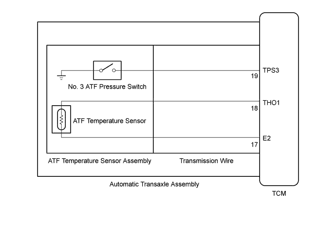
INSPECTION PROCEDURE
Refer to DTC P0711 Click here.
PROCEDURE
-
INSPECT TRANSMISSION WIRE (ATF TEMPERATURE SENSOR)
-
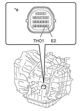
Text in Illustration *1 Component without TCM connected
(Transmission Wire)
Remove the TCM.
-
Measure the resistance according to the value(s) in the table below.
Standard Resistance Tester Connection Condition Specified Condition 18 (THO1) - 17 (E2) Always 79 Ω to 156 kΩ 18 (THO1) - Body ground Always 10 kΩ or higher 17 (E2) - Body ground Always 10 kΩ or higher Tech Tips
If the resistance is out of the specified range at any of the ATF temperatures shown in the table below, the driveability of the vehicle may decrease.
Resistance (Reference) ATF Temperature Specified Condition 10°C (50°F) 5 to 8 kΩ 25°C (77°F) 2.5 to 4.5 kΩ 110°C (230°F) 0.22 to 0.28 kΩ
NG 
INSPECT ATF TEMPERATURE SENSOR Click here
OK 
REPLACE TCM Click here
-
-
INSPECT ATF TEMPERATURE SENSOR
-
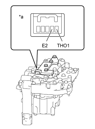
Text in Illustration *1 Component without harness connected
(ATF Temperature Sensor Assembly)
Disconnect the ATF temperature sensor connector.
-
Measure the resistance according to the value(s) in the table below.
Standard Resistance Tester Connection Condition Specified Condition THO1 - E2 Always 79 Ω to 156 kΩ THO1 - Body ground Always 10 kΩ or higher E2 - Body ground Always 10 kΩ or higher Tech Tips
If the resistance is out of the specified range at any of the ATF temperatures shown in the table below, the driveability of the vehicle may decrease.
Resistance (Reference) ATF Temperature Specified Condition 10°C (50°F) 5 to 8 kΩ 25°C (77°F) 2.5 to 4.5 kΩ 110°C (230°F) 0.22 to 0.28 kΩ
NG 
REPLACE ATF TEMPERATURE SENSOR (ATF TEMPERATURE SENSOR ASSEMBLY) Click here
OK
REPLACE TRANSMISSION WIRE Click here
-