ENGINE STOP AND START ECU INSTALLATION

-
INSTALL ENGINE STOP AND START ECU (for RHD)
-
Install the engine stop and start ECU with the 2 bolts.
- Torque:
- 13 N*m { 127 kgf*cm, 9 ft.*lbf }
-
Connect the 3 connectors to the engine stop and start ECU.
-
Connect the connector holder with the screw.
-
-
INSTALL ENGINE STOP AND START ECU (for LHD)
-
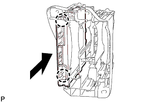
Engage the 2 claws to install the engine stop and start ECU to the ECU integration box RH.
-
-
INSTALL ECU INTEGRATION BOX RH (for LHD)
-
Install the ECU integration box RH with the 2 nuts and bolt.
Tech Tips
Refer to "SPECIFICATIONS - STANDARD BOLT" for the tightening torque.
-
Connect the 9 connectors and clamp.
-
-
INSTALL GLOVE COMPARTMENT DOOR ASSEMBLY
-
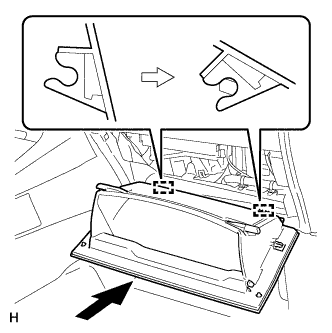
Attach the 2 hinges to install the glove compartment door.
-
Attach the glove compartment door stopper to the glove compartment door as shown in the illustration.
-
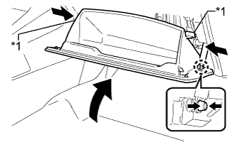
While pushing in the sides of the glove compartment door as indicated by the arrows in the illustration, close the glove compartment door to engage the 2 stoppers.
Text in Illustration *1 Stopper
-
-
INSTALL NO. 2 INSTRUMENT PANEL UNDER COVER SUB-ASSEMBLY
-
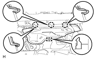
Attach the 3 claws and guide to install the No. 2 instrument panel under cover.
-
-
CONNECT CABLE TO NEGATIVE BATTERY TERMINAL
Note
When disconnecting the cable, some systems need to be initialized after the cable is reconnected Click here.
-
PERFORM REGISTRATION