CRUISE CONTROL SYSTEM (except 1WW) TC and CG Terminal Circuit
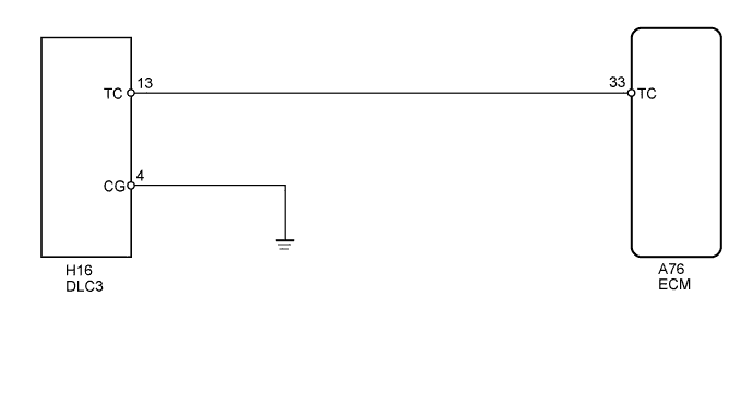
WIRING DIAGRAM
INSPECTION PROCEDURE
PROCEDURE
-
CHECK HARNESS AND CONNECTOR (DLC3 - ECM AND BODY GROUND)
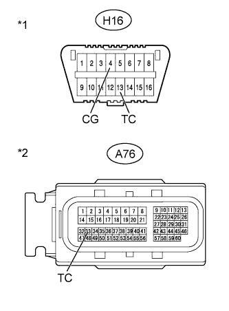
Text in Illustration *1 Front view of DLC3 *2 Front view of wire harness connector
(to ECM)
-
Disconnect the A76 ECM connector.
-
Measure the resistance according to the value(s) in the table below.
Standard Resistance Tester Connection Condition Specified Condition H16-13 (TC) - A76-33 (TC) Always Below 1 Ω H16-4 (CG) - Body ground H16-13 (TC) - Body ground Always 10 kΩ or higher
NG 
REPAIR OR REPLACE HARNESS OR CONNECTOR
OK 
PROCEED TO NEXT SUSPECTED AREA SHOWN IN PROBLEM SYMPTOMS TABLE Click here
-