DESCRIPTION
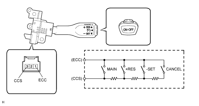
This circuit sends a signal to the ECM depending on the cruise control switch condition. The battery supplies positive (+) battery voltage to the cruise control switch. Terminal 40 (CCS)*1 or 23 (CCS)*2 of the ECM receives the voltage which varies according to the switch condition.
*1: for ZR Series Engine
*2: for AD Series Engine
INSPECTION PROCEDURE
PROCEDURE
- Click here
READ VALUE USING INTELLIGENT TESTER (CRUISE CONTROL SWITCH)
-
Use the Data List to check if the cruise control switch is functioning properly.
Table 1. Cruise Control Tester Display Measurement Item/Range Normal Condition Diagnostic Note Main SW M-CPU Cruise control switch (Main CPU) / ON or OFF ON: Cruise control switch on
OFF: Cruise control switch off
- Cancel Switch CANCEL switch signal / ON or OFF ON: CANCEL switch on
OFF: CANCEL switch off
- SET/COAST Switch -SET switch signal / ON or OFF ON: -SET switch on
OFF: -SET switch off
- RES/ACC Switch +RES switch signal / ON or OFF ON: +RES switch on
OFF: +RES switch off
- OK On screen, each item changes between ON and OFF according to above chart.
- OKClick here
- NGClick here
-
-
Click here
INSPECT SPIRAL CABLE SUB-ASSEMBLY
-
If there are any defects as follows, replace the spiral cable with a new one: scratches, cracks, dents or chips on the connector or spiral cable.
-
Check the spiral cable.
-
Set the spiral cable to the center position (Click here).
-
Rotate the spiral cable 2.5 times clockwise and measure the resistance according to the value(s) in the table below. Then rotate the spiral cable 5 times counterclockwise and measure the resistance according to the value(s) in the table below.
Note:As the spiral cable may break, do not rotate the spiral cable more than the specified amount.
Standard Resistance Tester Connection Condition Specified Condition 3 (CCS) - 1 (CCS) Always Below 1 Ω 4 (ECC) - 2 (ECC) -
Set the spiral cable to the center position and rotate the spiral cable 2.5 times clockwise. Then, while rotating the spiral cable 5 times counterclockwise, measure the resistance according to the value(s) in the table below.
Standard Resistance Tester Connection Condition Specified Condition 3 (CCS) - 1 (CCS) Always Below 1 Ω 4 (ECC) - 2 (ECC)
-
- OKClick here
- NGClick here
-
-
Click here
INSPECT CRUISE CONTROL SWITCH WIRE
-
Disconnect the z12 spiral cable connector.
-
Disconnect the z11 switch connector.
-
Measure the resistance according to the value(s) in the table below.
Standard Resistance Tester Connection Condition Specified Condition z12-3 (CCS) - z11-3 (CCS) Always Below 1 Ω z12-4 (ECC) - z11-1 (ECC) z12-3 (CCS) - Body ground Always 10 kΩ or higher z12-4 (ECC) - Body ground Table 2. Text in Illustration *1 Front view of wire harness connector
(to Spiral Cable)
*2 Front view of wire harness connector
(to Cruise Control Switch)
- OKClick here
- NGClick here
-
- Click here
INSPECT CRUISE CONTROL SWITCH
-
Remove the cruise control switch (Click here).
-
Measure the resistance according to the value(s) in the table below.
Standard Resistance Tester Connection Switch Condition Specified Condition 3 (CCS) - 1 (ECC) Cruise control switch on Below 2.5 Ω Cruise control switch off 1 MΩ or higher +RES switch held on 235 to 245 Ω +SET switch held on 617 to 643 Ω CANCEL switch held on 1509 to 1571 Ω
- OKClick here
- NGClick here
-
- Click here
CHECK HARNESS AND CONNECTOR (SPIRAL CABLE SUB-ASSEMBLY - ECM AND BODY GROUND)
-
Disconnect the H11 spiral cable connector.
-
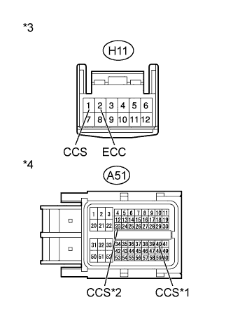
Disconnect the A51 ECM connector.
-
Measure the resistance according to the value(s) in the table below.
Standard Resistance Table 3. for ZR Series Engine Tester Connection Condition Specified Condition H11-1 (CCS) - A51-40 (CCS) Always Below 1 Ω H11-2 (ECC) - Body ground H11-1 (CCS) - Body ground Always 10 kΩ or higher Table 4. for AD Series Engine Tester Connection Condition Specified Condition H11-1 (CCS) - A51-23 (CCS) Always Below 1 Ω H11-2 (ECC) - Body ground H11-1 (CCS) - Body ground Always 10 kΩ or higher Table 5. Text in Illustration *1 for ZR Series Engine *2 for AD Series Engine *3 Front view of wire harness connector
(to Spiral Cable)
*4 Front view of wire harness connector
(to ECM)
Table 6. Result Result Proceed to OK (for 1ZR-FAE) A OK (for 2ZR-FAE) B OK (for 1AD-FTV) C OK (for 2AD-FHV) D NG E
-
- Click here
PROCEED TO NEXT SUSPECTED AREA SHOWN IN PROBLEM SYMPTOMS TABLEClick here
- Click here
REPLACE SPIRAL CABLE SUB-ASSEMBLYClick here
- Click here
REPLACE CRUISE CONTROL SWITCH WIRE
- Click here
REPLACE CRUISE CONTROL SWITCHClick here
- Click here
REPLACE ECMClick here
- Click here
REPLACE ECMClick here
- Click here
REPLACE ECMClick here
- Click here
REPLACE ECMClick here
- Click here
REPAIR OR REPLACE HARNESS OR CONNECTOR