Click here
Click here
Click here
Click here
-
CHECK ECM
-
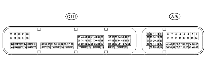
Disconnect the A76 and C111 ECM connectors.
-
Measure the voltage and resistance according to the value(s) in the table below.
Terminal No. (Symbol) Wiring Color Terminal Description Condition Specified Condition A76-1 (BATT) - Body ground P - Body ground Power source circuit Always 11 to 14 V A76-6 (IGSW) - Body ground B - Body ground IG power source circuit Ignition switch ON 11 to 14 V Ignition switch off Below 1 V A76-10 (ST1-) - Body ground R-L - Body ground Stop light switch signal circuit Ignition switch ON, brake pedal released 11 to 14 V Ignition switch ON, brake pedal depressed Below 1 V A76-9 (STP) - Body ground V - Body ground Stop light switch signal circuit Brake pedal depressed 11 to 14 V Brake pedal released Below 1 V A76-36 (CCS) - Body ground L - Body ground Cruise control switch circuit Cruise control switch on Below 2.5 Ω Cruise control switch off 10 MΩ or higher +RES switch held on 235 to 245 Ω -SET switch held on 617 to 643 Ω CANCEL switch held on 1509 to 1571 Ω C111-65 (D) - Body ground* B - Body ground Clutch switch signal circuit Ignition switch ON, clutch pedal depressed 11 to 14 V Ignition switch ON, clutch pedal released Below 1 V A76-32 (EC) - Body ground W-B - Body ground Ground Always Below 1 Ω C111-59 (E1) - Body ground BR - Body ground *: for Manual Transaxle
If the result is not as specified, there may be a malfunction on the wire harness side.
-