CRUISE CONTROL SYSTEM (for 1WW), Diagnostic DTC:C1A05

| DTC Code | DTC Name |
|---|---|
| C1A05 | Stop Light Switch Circuit |
DESCRIPTION
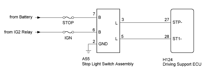
When the brake pedal is depressed, the stop light switch assembly sends a brake pedal operation signal to the driving support ECU. After reception of this signal, the driving support ECU cancels the radar cruise control system. When the driving support ECU detects a problem in the stop light switch circuit, DTC C1A05 is stored.
| DTC Code | DTC Detection Condition | Trouble Area |
|---|---|---|
| C1A05 | The voltages of terminals ST1- and STP of the driving support ECU are both below 1 V for 0.5 seconds or more. |
|
WIRING DIAGRAM
INSPECTION PROCEDURE
Note
-
Inspect the fuses for circuits related to this system before performing the following inspection procedure.
-
When replacing the driving support ECU, always replace it with a new one. If a driving support ECU which was installed to another vehicle is used, the information stored in the driving support ECU will not match the information from the vehicle. As a result, a DTC may be stored.
PROCEDURE
-
CHECK HARNESS AND CONNECTOR (STOP LIGHT SWITCH ASSEMBLY - BATTERY AND BODY GROUND)
-
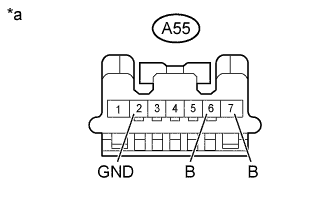
Text in Illustration *a Front view of wire harness connector
(to Stop Light Switch Assembly)
Disconnect the stop light switch assembly connector.
-
Measure the resistance according to the value(s) in the table below.
Standard Resistance Tester Connection Condition Specified Condition A55-2 (GND) - Body ground Always Below 1 Ω -
Measure the voltage according to the value(s) in the table below.
Standard Voltage Tester Connection Condition Specified Condition A55-6 (B) - Body ground Ignition switch ON 11 to 14 V Ignition switch off Below 1 V A55-7 (B) - Body ground Always 11 to 14 V
NG 
REPAIR OR REPLACE HARNESS OR CONNECTOR
OK 
-
-
CHECK HARNESS AND CONNECTOR (STOP LIGHT SWITCH ASSEMBLY - DRIVING SUPPORT ECU)
-
Disconnect the A55 stop light switch assembly connector.
-
Disconnect the H124 driving support ECU connector.
-
Measure the resistance according to the value(s) in the table below.
Standard Resistance Tester Connection Condition Specified Condition A55-5 (L) - H124-28 (ST1-) Always Below 1 Ω A55-3 (L) - H124-27 (STP-) A55-5 (L) or H124-28 (ST1-) - Body ground Always 10 kΩ or higher A55-3 (L) or H124-27 (STP-) - Body ground
NG
REPAIR OR REPLACE HARNESS OR CONNECTOR
OK
-
-
CHECK STOP LIGHT SWITCH ASSEMBLY
-
Temporarily replace the stop light switch assembly with a new or normally functioning one Click here.
-
Clear the DTCs Click here.
-
Check for the DTCs Click here.
OK DTC C1A05 is not output. Result Result Proceed to OK A NG (for LHD) B NG (for RHD) C
B
REPLACE DRIVING SUPPORT ECU Click here
C
REPLACE DRIVING SUPPORT ECU Click here
A 
END (STOP LIGHT SWITCH ASSEMBLY WAS DEFECTIVE)
-