- Click here
INSTALL STARTER ASSEMBLY
-
Install the starter assembly with the 2 bolts.
64 N*m 653 kgf*cm 47 ft.*lbf -
Connect the starter wire with the nut and close the terminal cap.
9.8 N*m 100 kgf*cm 87 in.*lbf -
Connect the starter connector.
-
- Click here
INSTALL NO. 3 AIR HOSE
Note:Before installation, remove any oil residue from the inside of pipe and hose.
-
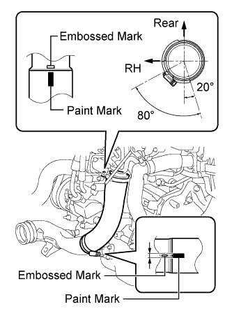
Align the paint mark of the No. 3 air hose with the embossed mark of the diesel throttle body assembly.
-
Align the paint mark of the No. 3 air hose with the embossed mark of the No. 2 air tube.
-
Tighten the clamp of the No. 3 air hose on the diesel throttle body assembly side.
6.5 N*m 66 kgf*cm 58 in.*lbf Tip:
-
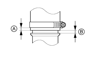
Align the paint mark of the air hose with the embossed mark and push in the air hose so that distance B is 0 to 2 mm (0 to 0.0787 in.).
-
Position the clamp so that distance A is 4 to 9 mm (0.157 to 0.354 in.).
-
-
Tighten the clamp of the No. 3 air hose on the No. 2 air tube side.
6.5 N*m 66 kgf*cm 58 in.*lbf Tip:
-
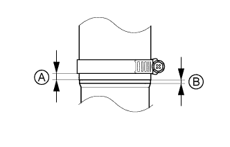
Align the paint mark of the air hose with the embossed mark and push in the air hose so that distance B is 0 to 2 mm (0 to 0.0787 in.).
-
Position the clamp so that distance A is 9 to 15 mm (0.354 to 0.591 in.).
-
-
- Click here
CONNECT NO. 2 VACUUM TRANSMITTING HOSE ASSEMBLY
-
Connect the No. 2 vacuum transmitting hose assembly to the intake manifold, and slide the clamp to secure it.
-
- Click here
INSTALL BATTERY CARRIER
-
Install the battery carrier with the 4 bolts.
19 N*m 189 kgf*cm 14 ft.*lbf -
Attach the 2 clamps to connect the wire harness.
-
- Click here
INSTALL BATTERY TRAY
- Click here
INSTALL BATTERY
- Click here
INSTALL BATTERY INSULATOR
- Click here
INSTALL BATTERY CLAMP SUB-ASSEMBLY
-
Attach the hook of the battery clamp sub-assembly to the battery carrier.
-
Partially tighten the nut and temporarily install the bolt.
-
Adjust the battery clamp sub-assembly position.
-
Tighten the nut and bolt.
for bolt 17 N*m 168 kgf*cm 12 ft.*lbf for nut 3.5 N*m 36 kgf*cm 31 in.*lbf
-
- Click here
INSTALL RADIATOR SUPPORT OPENING COVER
-
Attach the 4 hooks to install the radiator support opening cover.
-
Install the 3 clips.
-
- Click here
INSTALL NO. 1 ENGINE COVER
-
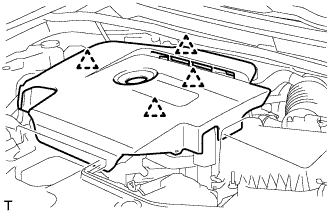
Attach the 4 clips to install the No. 1 engine cover.
-
- Click here
CONNECT CABLE TO POSITIVE BATTERY TERMINAL
- Click here
CONNECT CABLE TO NEGATIVE BATTERY TERMINAL
Note:When disconnecting the cable, some systems need to be initialized after the cable is reconnected (Click here).