GLOW PLUG INSTALLATION

-
INSTALL GLOW PLUG ASSEMBLY
-
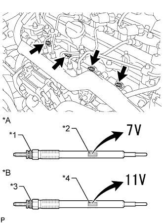
Text in Illustration *A for DPF *B for CCo *1 Color (White) *2 Mark (7V) *3 Color (Red) *4 Mark (11V) Check the insulator color and the mark on each glow plug assembly, and then, using a 10 mm deep socket wrench, install the 4 glow plugs.
- Torque:
- 12 N*m { 125 kgf*cm, 9 ft.*lbf }
Note
As the engine may be damaged, do not install any glow plug other than the type indicated in the illustration.
-
-
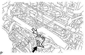
INSTALL NO. 1 GLOW PLUG CONNECTOR (for CCo)
-
Install the No. 1 glow plug connector with the 4 nuts.
- Torque:
- 2.2 N*m { 22 kgf*cm, 19 in.*lbf }
-
Connect the wire harness with the nut.
- Torque:
- 4.0 N*m { 41 kgf*cm, 35 in.*lbf }
-
Install the 5 grommets.
-
-
INSTALL NO. 1 GLOW PLUG CONNECTOR (for DPF)
-
Install the No. 1 glow plug connector with the 4 nuts.
- Torque:
- 2.2 N*m { 22 kgf*cm, 19 in.*lbf }
-
Attach the clamp to the bracket.
-
Install the 4 grommets.
-
-
CONNECT ENGINE WIRE
-
Connect the engine wire with the bolt.
- Torque:
- 13 N*m { 130 kgf*cm, 9 ft.*lbf }
-
for DPF:
Connect the glow connector.
-
-
INSTALL ENGINE COVER BRACKET
-
Install the engine cover bracket with the bolt and nut.
- Torque:
- for bolt
- 20 N*m { 204 kgf*cm, 15 ft.*lbf }
- for nut
- 8.4 N*m { 86 kgf*cm, 74 in.*lbf }
Text in Illustration 
Bolt 
Nut
-
-
INSTALL NO. 2 EGR PIPE SUB-ASSEMBLY
-
Install 2 new gaskets to the No. 2 EGR pipe sub-assembly and electric EGR control valve assembly.
-
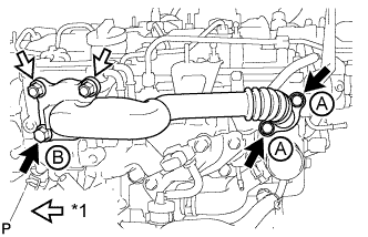
Text in Illustration *1 Nut Temporarily install the No. 2 EGR pipe sub-assembly with the 3 bolts and 2 nuts.
Standard Bolt Item Length Bolt A 25 mm (0.984 in.) Bolt B 70 mm (2.76 in.) -
Tighten the 2 bolts labeled A shown in the illustration.
- Torque:
- 24 N*m { 245 kgf*cm, 18 ft.*lbf }
-
Tighten the bolt labeled B and 2 nuts shown in the illustration.
- Torque:
- 24 N*m { 245 kgf*cm, 18 ft.*lbf }
-
Connect the electric EGR control valve connector.
-
-
INSTALL NO. 1 ENGINE COVER
-
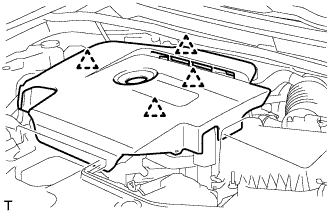
Attach the 4 clips to install the No. 1 engine cover.
-
-
CONNECT CABLE TO NEGATIVE BATTERY TERMINAL
Note
When disconnecting the cable, some systems need to be initialized after the cable is reconnected Click here.