| DTC Code | DTC Name |
|---|---|
| Vehicle Speed Signal Circuit between Radio Receiver and Combination Meter |
DESCRIPTION
- for Automatic Sound Levelizer (ASL):
-
This circuit is necessary for the Automatic Sound Levelizer (ASL) built into the radio and display receiver assembly.
-
The Automatic Sound Levelizer (ASL) function automatically adjusts the audio system volume level in order to compensate for increased vehicle noise (vehicle noise tends to increase as vehicle speed increases). The ASL adjusts the volume level based upon vehicle speed signals that it receives from the combination meter assembly.
- for "Bluetooth":
-
Vehicle speed signals are received from the combination meter assembly and used to cancel "Bluetooth" function operation.
-
The radio and display receiver assembly recognizes that the vehicle is being to driven and makes it impossible to connect or register a "Bluetooth" device while driving.
-
A voltage of 12 V or 5 V is output from each ECU and then input to the combination meter assembly. The signal is changed to a pulse signal at the transistor in the combination meter assembly. Each ECU controls the respective system based on the pulse signal.
-
If a short occurs in any of the ECUs or in the wire harness connected to an ECU, all systems in the following diagram will not operate normally.
INSPECTION PROCEDURE
PROCEDURE
- Click here
CHECK VEHICLE SIGNAL (OPERATION CHECK)
-
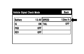
Enter the "Vehicle Signal Check Mode" screen. Refer to Check Vehicle Signal Check Mode in Operation Check (Click here).
-
While driving the vehicle, compare the "SPEED" indicator to the reading on the speedometer. Check if these readings are almost equal.
Tip:The combination meter assembly receives the vehicle speed signal from the skid control ECU via CAN communication. Therefore, perform the following inspection referring to values on the Data List of the skid control ECU because it is the source of the vehicle speed signal.
OK Vehicle speed displayed on the "Vehicle Signal Check Mode" screen is almost the same as the actual vehicle speed.
- OKClick here
- NGClick here
-
- Click here
PROCEED TO NEXT SUSPECTED AREA SHOWN IN PROBLEM SYMPTOMS TABLEClick here
- Click here
GO TO METER / GAUGE SYSTEMClick here