RADIATOR INSTALLATION

-
INSTALL FAN SHROUD
-
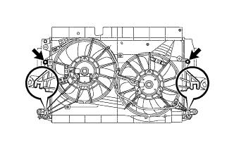
Insert the fan shroud hooks into the radiator holes and install the fan shroud with the 2 bolts.
- Torque:
- 7.0 N*m { 71 kgf*cm, 62 in.*lbf }
-
-
INSTALL INTERCOOLER ASSEMBLY
-
Install the intercooler assembly with the 4 bolts.
- Torque:
- 7.0 N*m { 71 kgf*cm, 62 in.*lbf }
-
-
INSTALL LOWER RADIATOR SUPPORT SUB-ASSEMBLY
-
Install the lower radiator support sub-assembly RH with the 2 bolts.
- Torque:
- 7.0 N*m { 71 kgf*cm, 62 in.*lbf }
-
Install the lower radiator support sub-assembly LH with the 2 bolts.
- Torque:
- 7.0 N*m { 71 kgf*cm, 62 in.*lbf }
-
-
INSTALL NO. 2 RADIATOR HOSE
-
Install the No. 2 radiator hose to the radiator assembly, and slide the hose clamp to secure the hose.
-
-
INSTALL RADIATOR ASSEMBLY
-
Install the 2 cushions.
-
Install the radiator assembly together with the intercooler assembly.
Note
Do not allow the radiator assembly to interfere with other parts.
-
Attach the clamp and connect the 2 connectors.
-
-
INSTALL CONDENSER ASSEMBLY WITH RECEIVER (w/ Air Conditioning System)
-
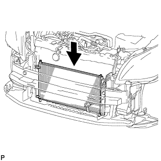
Install the condenser assembly with receiver as shown in the illustration.
Tech Tips
If the condenser is replaced with a new one, add compressor oil to the new condenser.
Capacity 40 cc (1.4 fl. oz.) Compressor oil ND-8 or equivalent
-
-
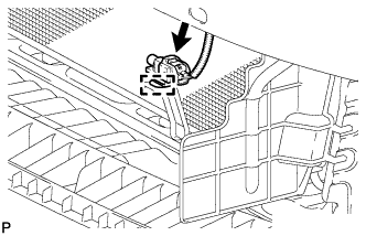
INSTALL HOOD LOCK SUPPORT SUB-ASSEMBLY
-
Install the hood lock support sub-assembly with the 4 bolts.
- Torque:
- 13 N*m { 127 kgf*cm, 9 ft.*lbf }
-
Attach the clamp to connect the hood lock control cable assembly to the hood lock support sub-assembly.
-
-
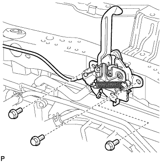
INSTALL HOOD LOCK ASSEMBLY
-
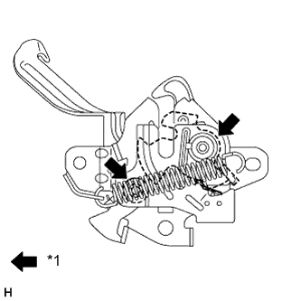
Text in Illustration *1 MP grease Apply MP grease to the sliding areas of the lock.
-
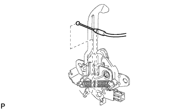
for LHD:
-
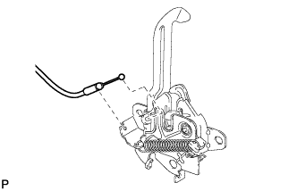
Connect the hood lock control cable.
-
Install the hood lock with the 3 bolts.
- Torque:
- 7.5 N*m { 76 kgf*cm, 66 in.*lbf }
-
-
for RHD:
-
Connect the hood lock control cable.
-
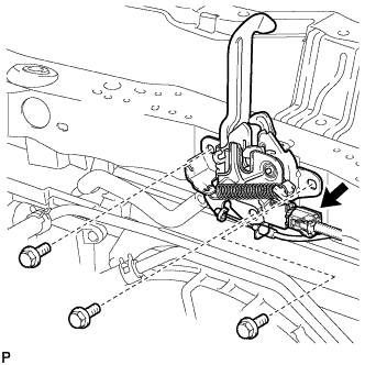
Connect the connector.
-
Install the hood lock with the 3 bolts.
- Torque:
- 7.5 N*m { 76 kgf*cm, 66 in.*lbf }
-
-
-
INSTALL UPPER RADIATOR SUPPORT SUB-ASSEMBLY
-
Install the 2 upper radiator support sub-assemblies with the 4 bolts.
- Torque:
- 7.0 N*m { 71 kgf*cm, 62 in.*lbf }
-
Install the 2 cushions.
-
-
INSTALL UPPER RADIATOR SUPPORT
-
Install the 2 upper radiator supports with the 2 bolts.
- Torque:
- 19 N*m { 194 kgf*cm, 14 ft.*lbf }
-
-
CONNECT AIR CONDITIONING TUBE AND ACCESSORY ASSEMBLY (w/ Air Conditioning System)
-
Remove the attached vinyl tape from the tube and connecting part of the cooler condenser assembly.
-
Sufficiently apply compressor oil to a new O-ring and the fitting surface of the tube joint.
Compressor oil ND-OIL 8 or equivalent -
Install the O-ring to the air conditioning tube and accessory assembly.
-
Connect the air conditioning tube and accessory assembly to the cooler condenser assembly with the bolt.
- Torque:
- 5.4 N*m { 55 kgf*cm, 48 in.*lbf }
-
-
CONNECT DISCHARGE HOSE SUB-ASSEMBLY (w/ Air Conditioning System)
-
Remove the attached vinyl tape from the pipe and connecting part of the cooler condenser assembly.
-
Sufficiently apply compressor oil to a new O-ring and the fitting surface of the hose joint.
Compressor oil ND-OIL 8 or equivalent -
Install the O-ring to the discharge hose sub-assembly.
-
Connect the discharge hose sub-assembly to the cooler condenser assembly with the bolt.
- Torque:
- 5.4 N*m { 55 kgf*cm, 48 in.*lbf }
-
-
CONNECT NO. 2 RADIATOR HOSE
Note
-
Check that the retainer is closed when the connector is inserted.
-
If replacing the hose, apply fresh engine coolant to the O-ring.
-
Push on the connector until it makes a click sound which indicates that the connection is complete. After connecting the connector, check that the connector cannot be disconnected by pulling the connector.
-
Do not use a quick connector that has been dropped.
-
Push in the retainer and connect the No. 2 radiator hose to the water inlet.
-
-
CONNECT NO. 3 AIR HOSE
-
Connect the No. 3 air hose to the intercooler assembly, and tighten the hose clamp to secure the hose.
- Torque:
- 6.5 N*m { 66 kgf*cm, 58 in.*lbf }
-
-
CONNECT INTERCOOLER AIR HOSE
Note
If replacing the intercooler air hose, check for deposits in the intercooler assembly and intercooler air hose. If necessary, wipe up deposits.
-
Connect the intercooler air hose to the intercooler assembly, and tighten the hose clamp to secure the hose.
- Torque:
- 6.5 N*m { 66 kgf*cm, 58 in.*lbf }
-
-
CONNECT NO. 1 RADIATOR HOSE
-
Connect the No. 1 radiator hose to the radiator assembly, and slide the hose clamp to secure the hose.
-
-
CONNECT NO. 3 WATER BY-PASS HOSE
-
Connect the No. 3 water by-pass hose to the radiator assembly, and slide the hose clamp to secure the hose.
-
Attach the clamp to connect the No. 3 water by-pass hose to the fan shroud.
-
-
CONNECT NO. 2 WATER BY-PASS HOSE
-
Attach the 3 clamps to connect the No. 2 water by-pass hose to the 2 hose clamp brackets and No. 1 water hose clamp bracket.
-
-
INSTALL NO. 2 RADIATOR SIDE AIR SEAL
-
Attach the 2 clamps to install the No. 2 radiator side air seal.
-
-
INSTALL NO. 1 RADIATOR SIDE AIR SEAL
-
Attach the 2 clamps to install the No. 1 radiator side air seal.
-
-
INSTALL LOW PITCHED HORN ASSEMBLY
-
Connect the horn connector to install the low pitched horn assembly.
-
Install the bolt.
- Torque:
- 20 N*m { 204 kgf*cm, 15 ft.*lbf }
-
-
CONNECT AMBIENT TEMPERATURE SENSOR
-
Attach the clamp to install the cooler thermistor (ambient temperature sensor).
-
Connect the connector.
-
-
INSTALL BATTERY CARRIER
-
Install the battery carrier with the 4 bolts.
- Torque:
- 19 N*m { 189 kgf*cm, 14 ft.*lbf }
-
Attach the 2 clamps to connect the engine wire.
-
-
INSTALL BATTERY TRAY
-
INSTALL BATTERY
-
INSTALL BATTERY INSULATOR
-
INSTALL BATTERY CLAMP SUB-ASSEMBLY
-
Attach the hook of the battery clamp sub-assembly to the battery carrier.
-
Partially tighten the nut and temporarily install the bolt.
-
Adjust the battery clamp sub-assembly position.
-
Tighten the nut and bolt.
- Torque:
- for bolt
- 17 N*m { 168 kgf*cm, 12 ft.*lbf }
- for nut
- 3.5 N*m { 36 kgf*cm, 31 in.*lbf }
-
-
CONNECT CABLE TO POSITIVE BATTERY TERMINAL
-
CONNECT CABLE TO NEGATIVE BATTERY TERMINAL
Note
When disconnecting the cable, some systems need to be initialized after the cable is reconnected Click here.
-
ADD ENGINE COOLANT
CAUTION:
Do not remove the reservoir cap and air release valve while the engine and radiator assembly are still hot. Pressurized, hot engine coolant and steam may be released and cause serious burns.
-
Tighten the radiator drain cock plug by hand.
-
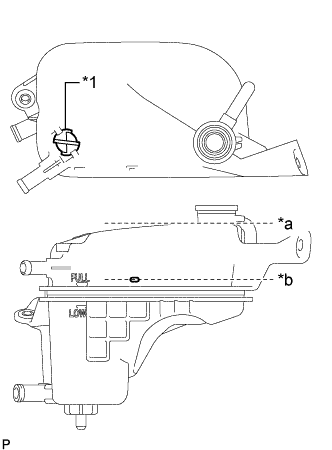
Text in Illustration *1 Air Release Valve *a Radiator Reservoir Assembly Filler Neck *b Pour Limit Line Remove the air release valve.
-
Add engine coolant to the pour limit line of the radiator reservoir assembly.
Standard Capacity Item Specified Condition w/o Combustion Type Power Heater 7.0 liters (7.4 US qts, 6.2 Imp. qts) w/ Combustion Type Power Heater 7.3 liters (7.7 US qts, 6.4 Imp. qts) Note
Never use water as a substitute for engine coolant.
Tech Tips
Toyota recommends the use of approved "Toyota Premium Long Life Coolant for 1WW/2WW engines" or equivalent.
-
Press the No. 2 radiator hose and radiator hose sub-assembly several times by hand, and then check the level of the engine coolant.
If the coolant level is low, add engine coolant.
-
Install the air release valve.
-
Add engine coolant to the filler neck of the radiator reservoir assembly.
-
Install the reservoir cap.
-
Start the engine, and warm it up until the cooling fan operates.
Note
-
Before starting the engine, turn the A/C switch off.
-
Adjust the air conditioning temperature setting to MAX (HOT).
-
Adjust the air conditioning blower setting to Lo.
-
-
Maintain the engine speed at 2000 to 2500 rpm and warm up the engine until the cooling fan operates.
Note
-
Make sure that the radiator reservoir assembly still has some engine coolant in it.
-
Pay attention to the needle of the water temperature meter. Make sure that the needle does not show an abnormally high temperature.
-
If there is not enough engine coolant, the engine may burn out or overheat.
-
Immediately after starting the engine, if the radiator reservoir assembly does not have any coolant, perform the following: 1) stop the engine, 2) wait until the engine coolant has cooled down, and 3) add engine coolant until the coolant is filled to the pour limit line.
-
Until the coolant level has stabilized, run the engine at 2000 rpm.
-
-
Press the No. 2 radiator hose and radiator hose sub-assembly several times by hand to bleed air.
CAUTION:
-
Wear protective gloves.
-
Be careful as the radiator hoses are hot.
-
Keep your hands away from the cooling fan.
-
-
Stop the engine and wait until the coolant cools down to ambient temperature.
-
Check that the coolant level is between the FULL and LOW line.
If the coolant level is below the LOW line, repeat all of the procedures above.
If the coolant level is above the FULL line, drain coolant so that the coolant level is between the FULL and LOW line.
-
-
CHARGE REFRIGERANT (w/ Air Conditioning System)
- SST
- 09985-20010 ( 09985-02130, 09985-02150, 09985-02090, 09985-02110, 09985-02010, 09985-02050, 09985-02060, 09985-02070 )
-
Perform vacuum purging using a vacuum pump.
-
Charge refrigerant HFC-134a (R134a).
Standard 440 +/-30 g (15.5 +/-1.1 oz) 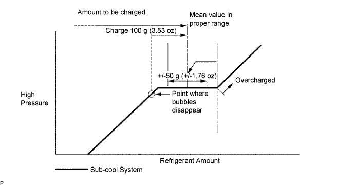
Note
-
Do not operate the cooler compressor before charging refrigerant as the cooler compressor will not work properly without any refrigerant, and will overheat.
-
Approximately 100 g (3.53 oz) of refrigerant may need to be charged after bubbles disappear. The refrigerant amount should be checked by measuring its quantity, and not with the sight glass.
-
-
WARM UP ENGINE (w/ Air Conditioning System)
-
Warm up the engine at less than 1850 rpm for 2 minutes or more after charging the refrigerant.
Note
Be sure to warm up the compressor by turning the A/C switch on after removing and installing the cooler refrigerant lines (including the compressor) to prevent damage to the compressor.
-
-
INSPECT FOR REFRIGERANT LEAK (w/ Air Conditioning System)
-
After recharging the refrigerant gas, check for refrigerant gas leakage using a halogen leak detector.
-
Perform the operation observing the following instructions:
-
Stop the engine.
-
Secure good ventilation (the halogen leak detector may react to volatile gases other than refrigerant, such as evaporated gasoline or exhaust gas).
-
Repeat the test 2 or 3 times.
-
Make sure that some refrigerant remains in the refrigeration system.
Tech Tips
When the compressor is off: approximately 392 to 588 kPa (4.0 to 6.0 kgf/cm2, 57 to 85 psi).
-
-
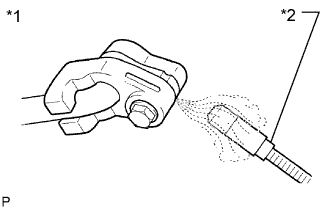
Text in Illustration *1 Check for Leakage *2 Halogen Leak Detector Using a halogen leak detector, check the refrigerant line for leakage.
-
If a gas leak is not detected from the drain hose, remove the blower motor control (blower resistor) from the cooling unit. Insert the halogen leak detector sensor into the unit and check for gas leakage.
-
Disconnect the pressure switch connector and wait for approximately 20 minutes. Bring the halogen leak detector close to the pressure switch and check for gas leakage.
-
-
INSPECT FOR COOLANT LEAK
-
Remove the reservoir cap.
CAUTION:
To avoid the danger of being burned, do not remove the reservoir cap while the engine and radiator assembly are still hot. Thermal expansion will cause hot engine coolant and steam to blow out from the radiator assembly.
-
Fill the radiator assembly with coolant, and then attach a radiator cap tester.
-
Warm up the engine.
-
Pump the radiator cap tester to 143 kPa (1.5 kgf/cm2, 20.7 psi), and then check that the pressure does not drop.
If the pressure drops, check the hoses, radiator assembly and engine water pump assembly for leakage.
If there are no signs of external coolant leaks, check the heater core, cylinder block and head.
-
Reinstall the reservoir cap.
-
-
INSTALL FRONT LOWER BUMPER ABSORBER
-
Insert the 2 hooks of the front lower bumper absorber into the installation holes in the body to install the front lower bumper absorber.
-
Install the 4 bolts.
-
Install the 2 clips.
-
-
INSTALL NO. 1 ENGINE UNDER COVER
-
Install the No. 1 engine under cover with the 11 clips and 6 bolts.
-
-
INSTALL NO. 1 ENGINE COVER
-
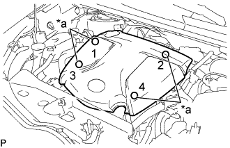
Text in Illustration *a Installation Points Attach the 4 clips to install the No. 1 engine cover.
Tech Tips
When attaching the clips, press the protrusions on the top of the No. 1 engine cover at the clip installation points.
-
-
INSTALL FRONT BUMPER REINFORCEMENT SUB-ASSEMBLY