INTAKE MANIFOLD REMOVAL

-
REMOVE RADIATOR ASSEMBLY
-
REMOVE DIESEL THROTTLE BODY ASSEMBLY
-
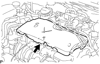
REMOVE ENGINE COVER
-
DISCONNECT ENGINE WIRE
-
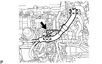
Detach the 2 clamps and disconnect the glow plug controller assembly harness connector.
-
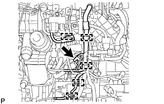
Detach the 5 clamps and disconnect the fuel quantity control valve connector.
-
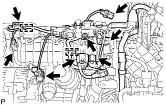
Disconnect the fuel pressure sensor connector.
-
Disconnect the engine coolant temperature sensor connector.
-
Disconnect the generator assembly connector.
-
Disconnect the camshaft position sensor connector.
-
Disconnect the turbo pressure sensor assembly connector.
-
Disconnect the 2 glow plug controller assembly connectors.
-
Detach the 2 clamps.
-
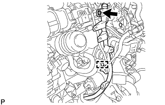
Using a T25 "TORX" socket wrench, remove the screw and disconnect the engine wire.
-
-
REMOVE ENGINE OIL LEVEL DIPSTICK GUIDE
-
Remove the engine oil level dipstick.
-
Detach the clamp and disconnect the fuel feed pipe sub-assembly from the engine oil level dipstick guide.
-
Using a T25 "TORX" socket wrench, remove the bolt and engine oil level dipstick guide.
-
Remove the O-ring from the engine oil level dipstick guide.
-
-
DISCONNECT NO. 2 VACUUM HOSE ASSEMBLY
-
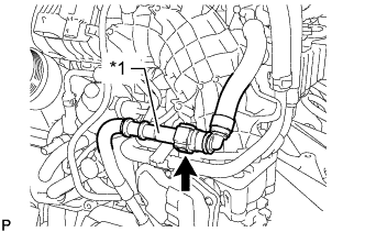
Text in Illustration *1 No. 1 Vacuum Pipe Disconnect the No. 2 vacuum hose assembly from the No. 1 vacuum pipe.
-
Check that there is no damage or foreign matter on the part of the No. 1 vacuum pipe that contacts the No. 2 vacuum hose assembly connector.
-
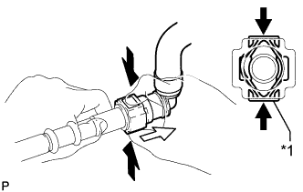
Text in Illustration *1 Retainer 
Pinch 
Pull Out If the No. 2 vacuum hose assembly connector and No. 1 vacuum pipe are stuck together, hold the No. 1 vacuum pipe by hand and push and pull on the No. 2 vacuum hose assembly connector.
Note
-
Check for any dirt and foreign matter contamination in the No. 1 vacuum pipe and around the No. 2 vacuum hose assembly connector. Clean if necessary. Foreign matter may damage the O-ring or cause leaks in the seal between the No. 1 vacuum pipe and No. 2 vacuum hose assembly connector.
-
Do not use any tools to separate the No. 1 vacuum pipe and No. 2 vacuum hose assembly connector.
-
Check for any dirt and foreign matter on the No. 1 vacuum pipe seal surface. Clean if necessary.
-
Protect the disconnected part by covering it with a plastic bag and tape after disconnecting the No. 2 vacuum hose assembly.
-
If the No. 1 vacuum pipe and No. 2 vacuum hose assembly connector are stuck together, pinch the No. 2 vacuum hose assembly connector between your fingers and turn it carefully to free it. Then disconnect the No. 2 vacuum hose assembly.
-
-
Check for dirt or mud on the No. 1 vacuum pipe seal surface of the disconnected No. 1 vacuum pipe. Clean if necessary.
-
To protect the disconnected No. 1 vacuum pipe and No. 2 vacuum hose assembly connector from damage and contamination, cover them with a plastic bag and tape.
-
-
-
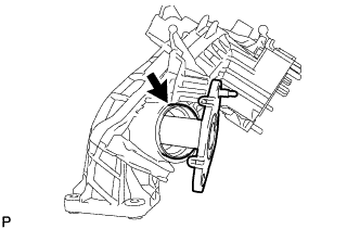
REMOVE NO. 1 VACUUM PIPE
-
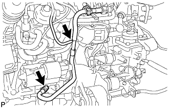
Disconnect the vacuum hose.
-
Using an E7 "TORX" socket wrench, remove the bolt and No. 1 vacuum pipe from the cylinder block sub-assembly.
-
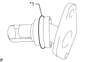
Remove the O-ring from the No. 1 vacuum pipe.
-
-
REMOVE INTAKE MANIFOLD
-
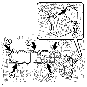
Remove the bolt labeled B and loosen the 6 bolts labeled A in the order shown in the illustration, and then remove the intake manifold.
Text in Illustration Bolt A Bolt B Tech Tips
The bolts labeled A in the illustration cannot be removed from the intake manifold.
-
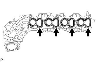
Remove the 4 gaskets from the intake manifold.
-
Remove the gasket from the No. 2 EGR pipe sub-assembly.
-
-
REMOVE TURBO PRESSURE SENSOR ASSEMBLY
-
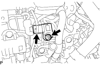
Disconnect the turbo pressure sensor connector.
-
Using a T27 "TORX" socket wrench, remove the bolt and turbo pressure sensor assembly.
-
-
REMOVE GLOW PLUG CONTROLLER ASSEMBLY
-
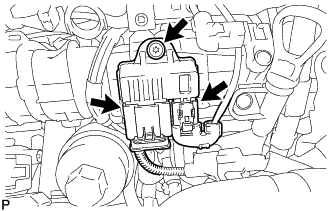
Disconnect the 2 connectors.
-
Using a T25 "TORX" socket wrench, remove the bolt and glow plug controller assembly.
-
-
REMOVE NO. 2 EGR PIPE SUB-ASSEMBLY
-
Remove the No. 2 EGR pipe sub-assembly from the intake manifold.
-
Text in Illustration *1 O-Ring Remove the O-ring from the No. 2 EGR pipe sub-assembly.
-