INTAKE MANIFOLD INSTALLATION

-
INSTALL ENGINE COVER JOINT
-
Install the engine cover joint.
- Torque:
- 8.0 N*m { 82 kgf*cm, 71 in.*lbf }
-
-
INSTALL NO. 1 GAS FILTER
-
Using a 24 mm deep socket wrench, install the No. 1 gas filter to the intake manifold.
- Torque:
- 17 N*m { 173 kgf*cm, 13 ft.*lbf }
-
Connect the air hose to the No. 1 gas filter.
-
-
INSTALL INTAKE MANIFOLD
-
w/ Stud Bolt:
Using an E6 "TORX" socket wrench, install the 2 stud bolts to the intake manifold.
- Torque:
- 5.0 N*m { 51 kgf*cm, 44 in.*lbf }
-
Install the wire harness clamp bracket to the intake manifold with the bolt.
- Torque:
- 15 N*m { 153 kgf*cm, 11 ft.*lbf }
-
Install a new gasket to the intake manifold.
-
Install the intake manifold and intake manifold stay with the 5 bolts and 2 nuts.
- Torque:
- 28 N*m { 286 kgf*cm, 21 ft.*lbf }
-
Connect the fuel vapor feed hose and ventilation hose.
-
Attach the 5 clamps to the intake manifold.
-
Install the wire harness clamp bracket with the bolt.
- Torque:
- 10 N*m { 102 kgf*cm, 7 ft.*lbf }
-
-
INSTALL NO. 1 VACUUM SWITCHING VALVE ASSEMBLY
-
Install the No. 1 vacuum switching valve assembly with the bolt.
- Torque:
- 10 N*m { 102 kgf*cm, 7 ft.*lbf }
-
Connect the connector and 2 vacuum hoses.
-
-
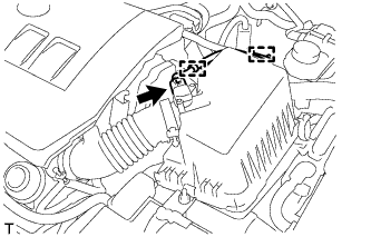
INSTALL VACUUM SENSOR ASSEMBLY
-
Connect the air hose to the vacuum sensor assembly.
-
Install the vacuum sensor assembly with the engine cover joint.
- Torque:
- 8.0 N*m { 82 kgf*cm, 71 in.*lbf }
-
Connect the vacuum sensor connector.
-
-
INSTALL THROTTLE BODY ASSEMBLY
Tech Tips
Perform "Inspection After Repairs" after replacing the throttle body assembly Click here.
-
Install a new gasket to the intake manifold.
-
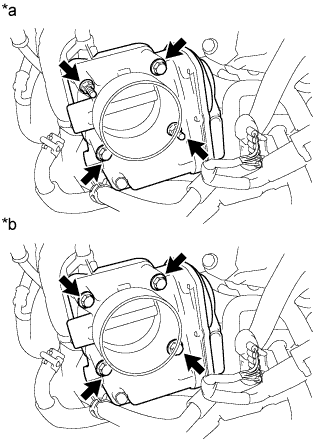
Text in Illustration *a for Type A *b for Type B for Type A:
Install the throttle body with the 2 bolts and 2 nuts.
- Torque:
- 10 N*m { 102 kgf*cm, 7 ft.*lbf }
-
for Type B:
Install the throttle body with the 4 bolts.
- Torque:
- 10 N*m { 102 kgf*cm, 7 ft.*lbf }
-
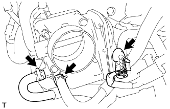
Connect the throttle body connector and 2 water hoses.
-
-
INSTALL AIR CLEANER CAP SUB-ASSEMBLY
-
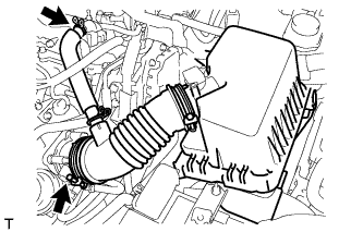
Connect the air cleaner cap with the band.
-
Connect the PCV hose.
-
Connect the 2 clamps.
-
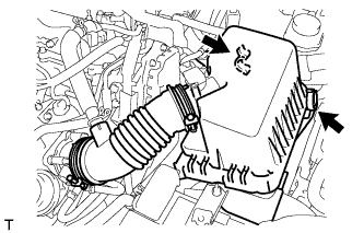
Attach the 2 clamps and connect the wire harness.
-
Connect the mass air flow meter connector.
-
-
INSTALL GENERATOR ASSEMBLY
-
ADD ENGINE COOLANT
-
Tighten the radiator drain cock plug.
-
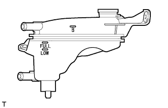
Add TOYOTA Super Long Life Coolant (SLLC) through the radiator reservoir filler opening until the coolant reaches the B line.
Standard Capacity Item Specified Condition for Manual transaxle 5-bladed fan 5.6 liters (5.9 US qts, 4.9 Imp. qts) 7-bladed fan 6.3 liters (6.7 US qts, 5.5 Imp. qts) for CVT 6.2 liters (6.6 US qts, 5.4 Imp. qts) Tech Tips
TOYOTA vehicles are filled with TOYOTA SLLC at the factory. In order to avoid damage to the engine cooling system and other technical problems, only use TOYOTA SLLC or similar high quality ethylene glycol based non-silicate, non-amine, non-nitrite, non-borate coolant with long-life hybrid organic acid technology (coolant with long-life hybrid organic acid technology is a combination of low phosphates and organic acids).
Note
Never use water as a substitute for engine coolant.
-
Squeeze the inlet and outlet radiator hoses several times by hand, and then check the level of the coolant.
If the coolant level is low, add coolant.
-
Install the cap and warm up the engine sufficiently.
-
Bleed air from the cooling system.
Note
-
Before starting the engine, turn the A/C switch off.
-
Adjust the air conditioning temperature setting to MAX (HOT).
-
Adjust the air conditioning blower setting to Lo.
-
Warm up the engine until the thermostat opens. While the thermostat is open, allow the coolant to circulate for several minutes.
Tech Tips
The thermostat opening timing can be confirmed by squeezing the inlet radiator hose by hand, and sensing vibrations when the engine coolant starts to flow inside the hose.
CAUTION:
When squeezing the radiator hose:
-
Wear protective gloves.
-
Be careful as the radiator hoses are hot.
-
Keep your hands away from the radiator fan.
-
-
After the engine has warmed up, repeat the following procedure for at least 7 minutes: run the engine at 3000 rpm for 5 seconds, and then at idle speed for 45 seconds (repeat this procedure at least 8 times).
-
Squeeze the inlet and outlet radiator hoses several times by hand to bleed air from the system.
CAUTION:
When squeezing the radiator hose:
-
Wear protective gloves.
-
Be careful as the radiator hoses are hot.
-
Keep your hands away from the radiator fan.
-
-
-
After the engine has cooled down, check that the coolant level is between FULL and LOW lines.
If the coolant level is low, add coolant to the FULL line on the reservoir.
-
-
INSPECT FOR ENGINE COOLANT LEAK
CAUTION:
To avoid being burned, do not remove the radiator reservoir cap while the engine and radiator are still hot. Thermal expansion may cause hot engine coolant and steam to blow out from the radiator.
-
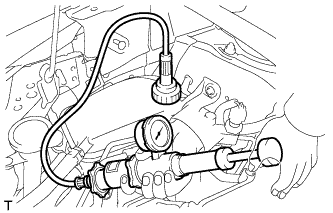
Fill the radiator with engine coolant, and then attach a radiator cap tester.
-
Warm up the engine.
-
Using the radiator cap tester, increase the pressure inside the radiator to 118 kPa (1.2 kgf/cm2, 17 psi), and then check that the pressure does not drop.
If the pressure drops, check the hoses, radiator and water pump for leakage. If there are no signs or traces of external engine coolant leakage, check the heater core, cylinder block and head.
-