EXHAUST MANIFOLD INSTALLATION

-
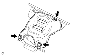
INSTALL NO. 2 EXHAUST MANIFOLD HEAT INSULATOR
-
Install the heat insulator with the 3 bolts.
- Torque:
- 12 N*m { 122 kgf*cm, 9 ft.*lbf }
-
-
INSTALL EXHAUST MANIFOLD
-
Install a new exhaust manifold gasket.
-
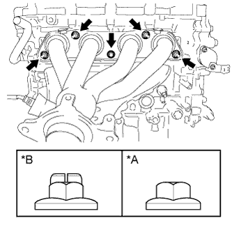
Text in Illustration *A Nut Type A *B Nut Type B Install the exhaust manifold with the 5 nuts.
- Torque:
- Type A
- 21 N*m { 214 kgf*cm, 15 ft.*lbf }
- Type B
- 37 N*m { 377 kgf*cm, 27 ft.*lbf }
-
-
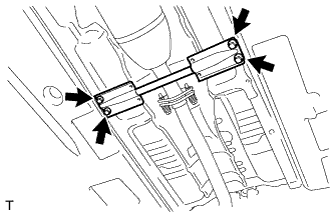
INSTALL MANIFOLD STAY
-
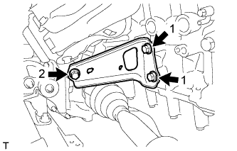
Temporarily install the manifold stay with the 3 bolts.
-
While pushing the manifold stay toward the exhaust manifold, tighten the 2 bolts labeled 1.
- Torque:
- 43 N*m { 438 kgf*cm, 32 ft.*lbf }
-
Tighten the bolt labeled 2.
- Torque:
- 43 N*m { 438 kgf*cm, 32 ft.*lbf }
-
-
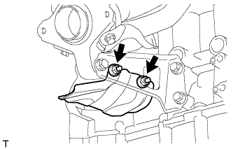
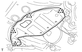
INSTALL DRIVE SHAFT HEAT INSULATOR SUB-ASSEMBLY
-
Install the heat insulator with the 2 nuts.
- Torque:
- 18 N*m { 179 kgf*cm, 13 ft.*lbf }
-
-
INSTALL FRONT EXHAUST PIPE ASSEMBLY
-
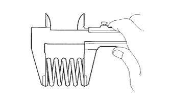
Using a vernier caliper, measure the free length of the compression springs.
Minimum Free Length Item Specified Condition Front side 43 mm (1.69 in.) Rear side 40 mm (1.57 in.) If the free length is less than the minimum, replace the compression spring.
-
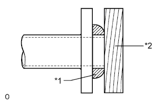
Text in Illustration *1 Gasket *2 Wooden Block Using a plastic-faced hammer and wooden block, tap in a new gasket until its surface is flush with the exhaust manifold.
Note
-
Be sure to install the gasket so that it faces the correct direction.
-
Do not reuse the gasket.
-
Do not damage the gasket.
-
When connecting the exhaust pipe, do not push in the gasket with the exhaust pipe.
-
-
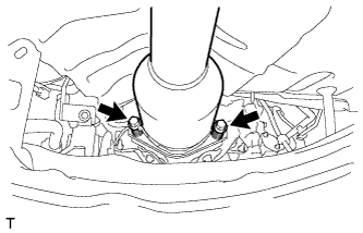
Install the 3 exhaust pipe supports, and then install the front exhaust pipe assembly with the 2 compression springs and 2 bolts.
- Torque:
- 43 N*m { 438 kgf*cm, 32 ft.*lbf }
-
Text in Illustration *1 Gasket *2 Wooden Block Using a plastic-faced hammer and wooden block, tap in a new gasket until its surface is flush with the front exhaust pipe assembly.
Note
-
Be sure to install the gasket so that it faces the correct direction.
-
Do not reuse the gasket.
-
Do not damage the gasket.
-
When connecting the exhaust pipe, do not push in the gasket with the exhaust pipe.
-
-
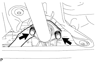
Connect the front exhaust pipe assembly to the tailpipe assembly with the 2 compression springs and 2 bolts.
- Torque:
- 43 N*m { 438 kgf*cm, 32 ft.*lbf }
-
Connect the heated oxygen sensor connector.
-
Attach the clamp to connect the heated oxygen sensor wire harness.
-
-
INSTALL FRONT FLOOR CENTER BRACE
-
Install the floor brace with the 4 bolts.
- Torque:
- 51 N*m { 520 kgf*cm, 38 ft.*lbf }
-
-
INSTALL NO. 2 ENGINE UNDER COVER
-
Install the under cover with the 4 clips.
-
-
INSTALL NO. 1 EXHAUST MANIFOLD HEAT INSULATOR
-
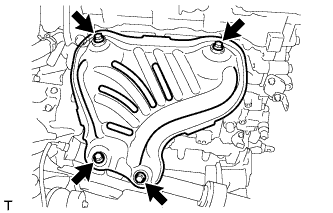
Install the heat insulator with the 4 bolts.
- Torque:
- 12 N*m { 122 kgf*cm, 9 ft.*lbf }
-
-
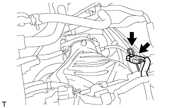
INSTALL WIRE HARNESS CLAMP BRACKET
-
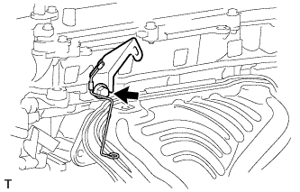
Install the bracket with the bolt.
- Torque:
- 60 N*m { 612 kgf*cm, 44 ft.*lbf }
-
-
INSTALL AIR FUEL RATIO SENSOR
-
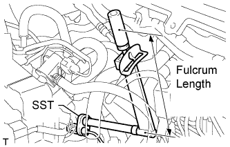
Using SST, install the sensor to the exhaust manifold.
- SST
- 09224-00010
- Torque:
- without SST
- 44 N*m { 449 kgf*cm, 32 ft.*lbf }
- with SST
- 40 N*m { 408 kgf*cm, 30 ft.*lbf }
Tech Tips
Use a torque wrench with a fulcrum length of 300 mm (11.8 in.).
Note
Do not damage the sensor.
-
Connect the sensor connector and clamp.
-
-
INSTALL OUTER COWL TOP PANEL
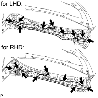
-
Install the outer cowl top panel with the 9 bolts.
- Torque:
- 8.8 N*m { 90 kgf*cm, 78 in.*lbf }
-
Connect the connector clamp.
-
-
INSTALL WINDSHIELD WIPER MOTOR AND LINK
-
Install the windshield wiper motor and link Click here.
-
-
INSTALL NO. 2 CYLINDER HEAD COVER
-
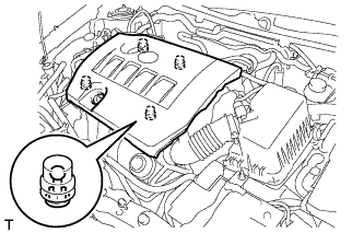
Attach the 4 clips to install the cover.
Note
-
Be sure to attach the clips securely.
-
Do not apply excessive force or hit the cover to attach the clips. This may cause the cover to break.
-
-
-
INSPECT FOR EXHAUST GAS LEAK
If gas is leaking, tighten the areas necessary to stop the leak. Replace damaged parts as necessary.