- Click here
INSTALL EXHAUST GAS TEMPERATURE SENSOR (for Sensor 1)
Note:If the exhaust gas temperature sensor is dropped, replace it with a new one.
-
Using a 14 mm union nut wrench, install the exhaust gas temperature sensor.
30 N*m 306 kgf*cm 22 ft.*lbf Note:Use the formula to calculate special torque values for situations where a union nut wrench is combined with a torque wrench (Click here).
-
- Click here
INSTALL NO. 1 TURBO INSULATOR
-
Install the No. 1 turbo insulator with the 3 bolts and nut.
8.0 N*m 82 kgf*cm 71 in.*lbf
-
- Click here
CONNECT VACUUM CONTROL VALVE BRACKET
-
Using a T20 "TORX" socket wrench, connect the vacuum control valve bracket with the 3 screws.
-
Attach the air fuel ratio sensor clamp to the vacuum control valve bracket.
-
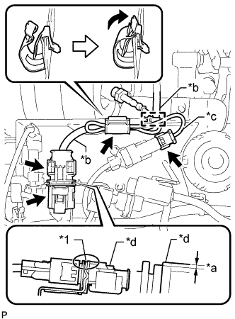
Move the clamp as shown in the illustration, and secure the air fuel ratio sensor and exhaust gas temperature sensor with the clamp.
Table 1. Text in Illustration *1 Vacuum Control Valve Bracket *a 1.5 mm (0.0591 in.) or less *b Air Fuel Ratio Sensor Connector Wire *c Exhaust Gas Temperature Sensor Connector Wire *d Air Fuel Ratio Sensor Connector Note:The wire harness may become damaged if not installed when the clamp is open.
-
Lower the air fuel ratio sensor connector to the position shown in the illustration.
-
Connect the air fuel ratio sensor connector.
-
Connect the exhaust gas temperature sensor connector.
-
Attach the wire harness clamp.
-
Connect the exhaust gas temperature sensor connector.
-
- Click here
INSPECT FOR EXHAUST GAS LEAK
If gas is leaking, tighten the areas necessary to stop the leak. Replace damaged parts as necessary.
- Click here
INSTALL NO. 1 ENGINE COVER
-
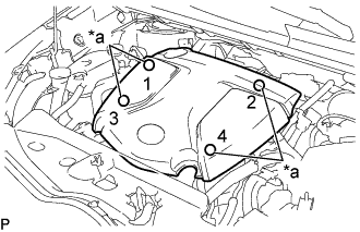
Attach the 4 clips to install the No. 1 engine cover.
Tip:When attaching the clips, press the protrusions on the top of the No. 1 engine cover at the clip installation points.
Table 2. Text in Illustration *a Installation Points
-