EXHAUST GAS TEMPERATURE SENSOR (for Sensor 1) REMOVAL

-
REMOVE NO. 1 ENGINE COVER
-
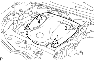
Lift the No. 1 engine cover to detach the 4 clips in the order shown in the illustration and remove the No. 1 engine cover.
Note
Attempting to disengage both front and rear clips at the same time may cause the No. 1 engine cover to break.
-
-
DISCONNECT SENSOR INSULATOR
-
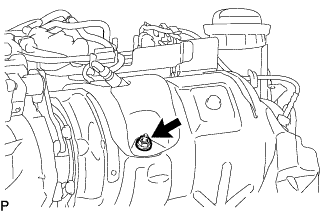
Remove the nut and disconnect the sensor insulator.
-
-
DISCONNECT VACUUM CONTROL VALVE BRACKET
-
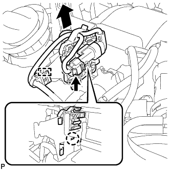
Disconnect the differential pressure sensor connector.
-
Detach the wire harness clamp.
-
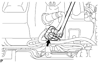
Remove the claw as shown in the illustration, and then slide the bracket clamp with differential pressure sensor to disconnect the bracket clamp with differential pressure sensor from the vacuum control valve bracket.
-
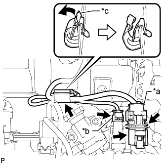
Text in Illustration *a Air Fuel Ratio Sensor Connector *b Exhaust Gas Temperature Sensor Connector *c Clamp Disconnect the exhaust gas temperature sensor connector.
-
Disconnect the air fuel ratio sensor connector.
-
Raise the air fuel ratio sensor connector from the vacuum control valve bracket.
-
Move the clamp as shown in the illustration, and disconnect the air fuel ratio sensor and exhaust gas temperature sensor.
Note
Disconnect the sensors while opening the clamp.
-
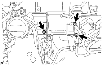
Using a T45 "TORX" socket wrench, remove the 3 screws and disconnect the vacuum control valve bracket.
-
-
REMOVE EXHAUST GAS TEMPERATURE SENSOR (for Sensor 1)
Note
If the exhaust gas temperature sensor is dropped, replace it with a new one.
-
Using a 14 mm union nut wrench, remove the exhaust gas temperature sensor.
-