Click here
Click here
- Click here
REMOVE NO. 1 ENGINE COVER
-
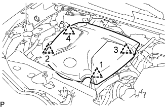
Lift the No. 1 engine cover to detach the 4 clips in the order shown in the illustration and remove the No. 1 engine cover.
Note:Attempting to disengage both front and rear clips at the same time may cause the No. 1 engine cover to break.
-
- Click here
REMOVE VACUUM SWITCHING VALVE ASSEMBLY
-
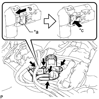
Slide the white-colored lock of the vacuum switching valve assembly connector as shown in the illustration to release it and disconnect the vacuum switching valve assembly connector.
Table 1. Text in Illustration *a White-colored Lock *b Slide *c Push -
Disconnect the 2 vacuum hoses.
-
Remove the 2 nuts and vacuum switching valve assembly.
-