FUEL FILTER REPLACEMENT

Note
When working on the fuel circuit, protect the generator assembly against dirt contamination.
Cover the generator assembly with suitable materials.
Failure to comply with this procedure may result in a generator assembly malfunction.
-
REMOVE AIR CLEANER CAP SUB-ASSEMBLY WITH AIR CLEANER HOSE ASSEMBLY
-
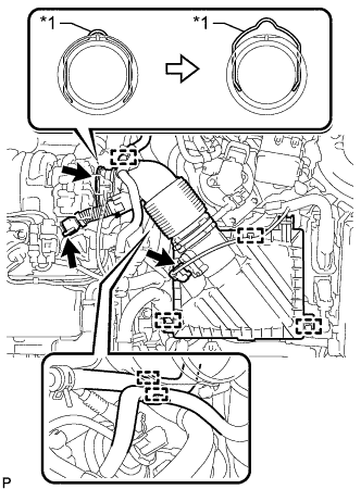
Text in Illustration *1 Retainer Detach the clamp and disconnect the mass air flow meter sub-assembly connector.
-
Detach the clamp and disconnect the vacuum hose from the air cleaner hose assembly.
-
Detach the clamp and disconnect the No. 1 fuel hose from the air cleaner hose assembly.
-
Detach the clamp and disconnect the No. 2 fuel hose from the air cleaner hose assembly.
-
Disconnect the ventilation hose from the cylinder head cover sub-assembly.
-
Release the retainer and disconnect the air cleaner hose assembly from the turbocharger sub-assembly as shown in the illustration.
-
Detach the 2 clamps and remove the air cleaner cap sub-assembly with air cleaner hose assembly.
-
-
REMOVE AIR CLEANER FILTER ELEMENT SUB-ASSEMBLY
-
REMOVE AIR CLEANER CASE SUB-ASSEMBLY
-

Remove the 3 bolts and air cleaner case sub-assembly.
-
-
REMOVE FUEL FILTER ASSEMBLY
-
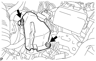
Remove the 2 nuts and No. 1 fuel filter protector.
-
Remove the No. 2 fuel pipe clamp from the No. 1 fuel hose.
-

Disconnect the No. 1 fuel hose and No. 3 fuel hose from the fuel filter assembly Click here.
-

Disconnect the connector from the fuel filter assembly.
-
Remove nut and fuel filter assembly from the fuel filter support.
-
Remove the bolt and fuel filter cover from the fuel filter assembly.
-
-
DRAIN FUEL
-
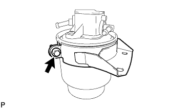
Loosen the drain cock and drain the fuel from the fuel filter assembly.
-
-
INSTALL FUEL FILTER ASSEMBLY
-
Install the fuel filter cover to a new fuel filter assembly with the bolt.
- Torque:
- 7.0 N*m { 71 kgf*cm, 62 in.*lbf }
-
Install the fuel filter assembly to the fuel filter support with the nut.
- Torque:
- 18 N*m { 178 kgf*cm, 13 ft.*lbf }
-
Connect the connector to the fuel filter assembly.
-
Connect the No. 1 fuel hose and No. 3 fuel hose to the fuel filter assembly Click here.
-
Install the No. 2 fuel pipe clamp to the No. 1 fuel hose.
-
Install the No. 1 fuel filter protector with the 2 nuts.
- Torque:
- 18 N*m { 178 kgf*cm, 13 ft.*lbf }
-
-
INSTALL AIR CLEANER CASE SUB-ASSEMBLY
-
Install the air cleaner case sub-assembly with the 3 bolts.
- Torque:
- 7.0 N*m { 71 kgf*cm, 62 in.*lbf }
-
-
INSTALL AIR CLEANER FILTER ELEMENT SUB-ASSEMBLY
-
INSTALL AIR CLEANER CAP SUB-ASSEMBLY WITH AIR CLEANER HOSE ASSEMBLY
-
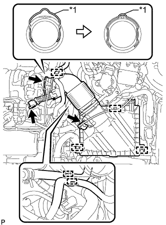
Text in Illustration *1 Retainer Connect the air cleaner hose assembly to the turbocharger sub-assembly and lock the retainer as shown in the illustration.
-
Attach the 2 clamps to install the air cleaner cap sub-assembly.
-
Connect the ventilation hose to the cylinder head cover sub-assembly.
-
Attach the clamp and connect the No. 2 fuel hose to the air cleaner hose assembly.
-
Attach the clamp and connect the No. 1 fuel hose to the air cleaner hose assembly.
-
Attach the clamp and connect the vacuum hose to the air cleaner hose assembly.
-
Attach the clamp and connect the mass air flow meter sub-assembly connector.
-
-
INSPECT FOR FUEL LEAK
-
Check fuel pump operation.
-
Connect the GTS to the DLC3.
-
Turn the ignition switch to ON and turn the GTS on.
Note
Do not start the engine.
-
Enter the following menus: Powertrain / Engine and ECT / Active Test / Actuator Test of FPC (EU5).
-
Check for pressure in the fuel inlet tube from the fuel line. Check that sounds of fuel flowing from the fuel tank can be heard. If no sounds can be heard, check the No. 1 integration relay, fuel suction with pump and gauge tube assembly, ECM and wiring connectors.
-
-
Inspect for fuel leaks.
-
Check that there are no fuel leaks from the fuel system after doing any maintenance or repairs. If there is a fuel leak, repair or replace parts as necessary.
-
-
Turn the ignition switch off.
-
Disconnect the GTS from the DLC3.
-