COMMON RAIL INSTALLATION

Note
-
Always be sure to check the tightening torque.
-
If the pressure lines are leaking after installation, they must be replaced.
-
Do not overtighten the pressure lines.
-
INSTALL FUEL PRESSURE SENSOR
-
Check the threads and sealing surfaces for damages prior to installing the fuel pressure sensor.
-
Make sure the fuel pressure sensor, sealing surfaces and threads are free from dirt and any foreign matter before performing work. Lightly grease the threads on the fuel pressure sensor.
-
Screw in the fuel pressure sensor by hand. Then tighten the fuel pressure sensor.
- Torque:
- 70 N*m { 714 kgf*cm, 52 ft.*lbf }
-
-
INSTALL COMMON RAIL ASSEMBLY
-
Install the common rail assembly to the cylinder head cover sub-assembly.
-
Using an E10 "TORX" socket wrench, install the 2 common rail assembly brackets with the 4 bolts.
Tech Tips
Refer to "SPECIFICATIONS - STANDARD BOLT" for the tightening torque.
-
Connect the fuel pressure sensor connector.
-
-
INSTALL FUEL INLET PIPE SUB-ASSEMBLY
Note
-
If the pressure lines are leaking after installation, they must be replaced.
-
Do not overtighten the pressure lines.
-
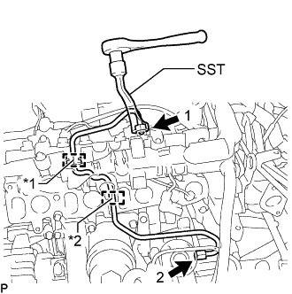
Text in Illustration *1 Rubber Grommet *2 Rubber Mount Install the fuel inlet pipe sub-assembly to the rubber grommet and rubber mount as shown in the illustration.
Note
Install the rubber mount and rubber grommet at the correct positions on the pressure line.
-
Temporarily install the union nut at the fuel supply pump assembly end and common rail assembly end of the fuel inlet pipe sub-assembly by hand.
-
Using SST, tighten the union nut at the fuel supply pump assembly end and common rail assembly end of the fuel inlet pipe sub-assembly as shown in the illustration.
SST PZ4TB-04959-10 - Torque:
- 24 N*m { 245 kgf*cm, 18 ft.*lbf }
Note
Reset SST in a timely manner to prevent bending of pressure lines.
-
-
INSTALL INJECTION PIPE SUB-ASSEMBLY
-
INSTALL INTAKE MANIFOLD
-
INSPECT FOR FUEL LEAK
Tech Tips
Using the intelligent tester to perform Active Tests allow relays, VSVs, actuators and other items to be operated without removing any parts. This non-intrusive functional inspection can be very useful because intermittent operation may be discovered before parts or wiring is disturbed. Performing Active Tests early in troubleshooting is one way to save diagnostic time. Data List information can be displayed while performing Active Tests.
-
Perform Active Test.
-
Connect the intelligent tester to the DLC3.
-
Turn the ignition switch to ON.
-
Start the engine.
-
Turn the intelligent tester on.
-
Enter the following menus: Powertrain / Engine / Active Test.
-
Perform the Active Test.
Tester Display Test Part Control Range Diagnostic Notes Test the Fuel Leak Pressurizes common rail internal fuel pressure, and checks for fuel leaks Stop/Start Performs inspection of the high pressure fuel system.
-
Engine Speed: 2050 rpm
-
Fuel Pressure: 172000 kPa
-
Target Common Rail Pressure: 176000 kPa
-
Target Pump SCV Current: 1400 mA
-
MAP: 176 kPa
-
MAF: 39 g/sec.
-
-
-