FUEL INJECTOR INSTALLATION

Note
-
Always be sure to check the tightening torque.
-
If the pressure lines are leaking after installation, they must be replaced.
-
Do not overtighten the pressure lines.
Tech Tips
Perform "Inspection After Repairs" after replacing the fuel injector assembly Click here.
-
INSTALL INJECTOR ASSEMBLY
Note
-
Before installing the injector assembly, check for carbon, foreign matter, etc. on the seal surfaces of the cylinder head sub-assembly and injector assembly. If there is foreign matter, remove it before installing the injector assembly.
-
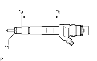
Make sure to replace the copper sealing ring on the injector assembly.
Text in Illustration *1 Copper Sealing Ring *a Point Above the Copper Sealing Ring *b Injector Assembly Slot End -
Before installing the injector assemblies to the injector assembly slots, apply a light coat of highly heat-resistant grease from above the top of the copper sealing ring to the injector assembly slot end.
-
Check the installation position of the high pressure connection.
-
Make sure to read the adjustment values each time new injector assemblies are installed.
Tech Tips
Perform "Inspection After Repairs" after replacing the fuel injector assembly Click here.
-
Install the 4 injector assemblies to the cylinder head cover sub-assembly.
-
Using an E10 "TORX" socket wrench, install the 4 clamping claws to the 4 injector assemblies with the 4 centering rings and 4 bolts.
- Torque:
- 10 N*m { 102 kgf*cm, 7 ft.*lbf }
Note
-
Retighten the clamping claw (cylinder head cover mounting).
-
Make sure the screw centering ring is correctly positioned in order to align the clamping claw.
-
Connect the 4 injector assembly connectors.
-
-
CONNECT NOZZLE LEAKAGE PIPE ASSEMBLY
-
Install 4 new sealing rings and connect the nozzle leakage pipe assembly.
-
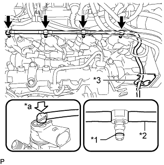
Text in Illustration *1 Sealing Ring *2 Leakage Line *3 Rubber Grommet *a Downward Connect the nozzle leakage pipe assembly to the rubber grommet.
-
Install 4 new sealing rings to the nozzle leakage pipe assembly.
-
Attach the connection of the nozzle leakage pipe assembly downwards.
-
-
Connect the connector and attach the 2 clamps to connect the wire harness.
-
-
INSTALL CAMSHAFT POSITION SENSOR
-
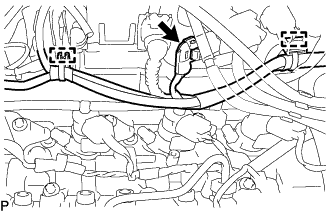
Apply a light coat of engine oil to the O-ring of the camshaft position sensor.
Note
-
When reusing the camshaft position sensor, inspect the O-ring.
-
Make sure that the O-ring is not cracked or jammed when installing the camshaft position sensor.
-
-
Using an E6 "TORX" socket wrench, install the camshaft position sensor with the bolt.
- Torque:
- 3.6 N*m { 37 kgf*cm, 32 in.*lbf }
-
Connect the camshaft position sensor connector.
-
-
INSTALL INJECTION PIPE SUB-ASSEMBLY
Note
-
If the pressure lines are leaking after installation, they must be replaced.
-
Do not overtighten the pressure lines.
-
Temporarily install the 2 No. 1 injection pipe sub-assemblies and 2 No. 2 injection pipe sub-assemblies at the common rail assembly end by hand.
-
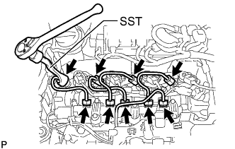
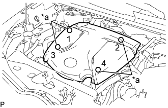
Using a SST, tighten the 4 union nuts at the common rail assembly end of the 2 No. 1 injection pipe sub-assemblies and 2 No. 2 injection pipe sub-assemblies as shown in the illustration.
SST PZ4TB-04959-10 - Torque:
- 24 N*m { 245 kgf*cm, 18 ft.*lbf }
Note
Reset SST in a timely manner to prevent bending of pressure lines.
-
Using SST, tighten the 4 union nuts at the 4 injector assembly ends of the 2 No. 1 injection pipe sub-assemblies and 2 No. 2 injection pipe sub-assemblies.
SST PZ4TB-04959-10 - Torque:
- 24 N*m { 245 kgf*cm, 18 ft.*lbf }
Note
Reset SST in a timely manner to prevent bending of pressure lines.
-
Check all components of the common rail system for tightness.
-
-
CONNECT CABLE TO NEGATIVE BATTERY TERMINAL
Note
When disconnecting the cable, some systems need to be initialized after the cable is reconnected Click here.
-
PERFORM REGISTRATION
-
Perform registration of injector compensation codes Click here.
-
-
INSTALL ENGINE COVER
-
INSTALL NO. 1 ENGINE COVER
-
Text in Illustration *a Installation Points Attach the 4 clips to install the No. 1 engine cover.
Tech Tips
When attaching the clips, press the protrusions on the top of the No. 1 engine cover at the clip installation points.
-
-
INSPECT FOR FUEL LEAK
Tech Tips
Using the intelligent tester to perform Active Tests allow relays, VSVs, actuators and other items to be operated without removing any parts. This non-intrusive functional inspection can be very useful because intermittent operation may be discovered before parts or wiring is disturbed. Performing Active Tests early in troubleshooting is one way to save diagnostic time. Data List information can be displayed while performing Active Tests.
-
Perform Active Test.
-
Connect the intelligent tester to the DLC3.
-
Turn the ignition switch to ON.
-
Start the engine.
-
Turn the intelligent tester on.
-
Enter the following menus: Powertrain / Engine / Active Test.
-
Perform the Active Test.
Tester Display Test Part Control Range Diagnostic Notes Test the Fuel Leak Pressurizes common rail internal fuel pressure, and checks for fuel leaks Stop/Start Performs inspection of the high pressure fuel system.
-
Engine Speed: 2050 rpm
-
Fuel Pressure: 172000 kPa
-
Target Common Rail Pressure: 176000 kPa
-
Target Pump SCV Current: 1400 mA
-
MAP: 176 kPa
-
MAF: 39 g/sec.
-
-
-