FUEL TANK INSTALLATION

-
INSTALL FUEL TANK RETURN TUBE SUB-ASSEMBLY
-
Attach the fuel tank return tube sub-assembly to the 3 clamps to install it.
-
-
INSTALL FUEL TANK MAIN TUBE SUB-ASSEMBLY
-
Attach the fuel tank main tube sub-assembly to the 4 clamps to install it.
-
-
INSTALL NO. 2 FUEL TANK MAIN TUBE SUB-ASSEMBLY (w/ Combustion Type Power Heater)
-
INSTALL FUEL TANK TO FILLER PIPE HOSE
-
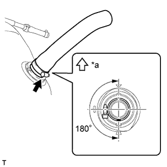
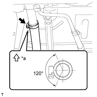
Text in Illustration *a Top Install the fuel tank to filler pipe hose to the fuel tank and tighten the hose clamp bolt so that the clamp is as shown in the illustration.
Note
Be sure to tighten the hose clamp so that it is at the correct angle.
Tech Tips
From the position in the illustration, the hose clamp can also be positioned so that the hose clamp bolt is on the opposite side of the hose with the bolt tip facing upwards.
-
-
INSTALL NO. 2 FUEL TANK CUSHION
-
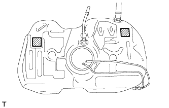
Install 2 new No. 2 fuel tank cushions at the locations shown in the illustration.
-
-
INSTALL NO. 1 FUEL TANK CUSHION
-
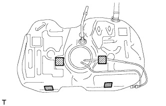
Install 4 new No. 1 fuel tank cushions at the locations shown in the illustration.
-
-
INSTALL FUEL TANK ASSEMBLY
-
Using a engine lifter, support the fuel tank assembly.
-
Raise the engine lifter and install the fuel tank assembly to the vehicle.
Note
-
Do not drop the fuel tank assembly.
-
When installing the fuel tank assembly, tilt it slightly to prevent it from interfering with the suspension arm or other surrounding parts.
-
-
Install the No. 1 fuel tank band sub-assembly RH and No. 1 fuel tank band sub-assembly LH with the 4 bolts.
- Torque:
- 39 N*m { 398 kgf*cm, 29 ft.*lbf }
-
w/ Combustion Type Power Heater:
Connect the No. 2 fuel tank main tube sub-assembly to the No. 2 fuel main tube and slide the clamp to secure it.
-
Connect the fuel tank main tube sub-assembly to the fuel main tube Click here.
-
Connect the fuel tank return tube sub-assembly to the fuel return tube Click here.
-
Connect the parking brake cable with the 2 bolts.
- Torque:
- 6.0 N*m { 61 kgf*cm, 53 in.*lbf }
-
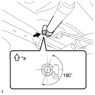
Text in Illustration *a Top Connect the breather hose to the fuel tank filler pipe and tighten the hose clamp bolt so that the clamp is as shown in the illustration.
Note
Be sure to tighten the hose clamp so that it is at the correct angle.
-
-
CONNECT FUEL TANK TO FILLER PIPE HOSE
-
Text in Illustration *a Top Connect the fuel tank to filler pipe hose to the fuel tank filler pipe and tighten the hose clamp bolt so that the clamp is as shown in the illustration.
Note
Be sure to tighten the hose clamp so that it is at the correct angle.
-
-
INSTALL NO. 1 FUEL TANK PROTECTOR
-
Install the fuel tank protector cushion.
-
Install the No. 1 fuel tank protector with the 4 clips.
-
-
INSTALL REAR FLOOR SIDE MEMBER BRACE SUB-ASSEMBLY
-
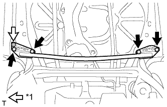
Text in Illustration *1 Clip Attach the clip and install the rear floor side member brace sub-assembly with the 4 bolts.
- Torque:
- 54 N*m { 551 kgf*cm, 40 ft.*lbf }
-
-
INSTALL REAR FLOOR SIDE MEMBER COVER LH
-
Install the rear floor side member cover LH with the nut and 2 bolts.
-
-
INSTALL REAR FLOOR SIDE MEMBER COVER RH
-
Install the rear floor side member cover RH with the nut and 2 bolts.
-
-
INSTALL FRONT FLOOR CENTER COVER LH
-
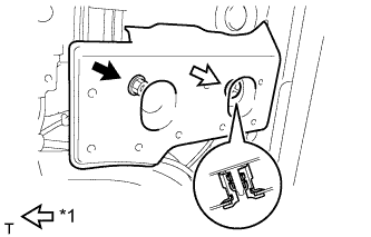
Text in Illustration *1 Grommet Attach the grommet and install the front floor center cover LH with the nut.
-
-
INSTALL FRONT FLOOR CENTER COVER RH
-
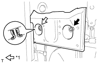
Text in Illustration *1 Grommet Attach the grommet and install the front floor center cover RH with the nut.
-
-
ADD FUEL
-
INSTALL FUEL SUCTION WITH PUMP AND GAUGE TUBE ASSEMBLY
-
INSTALL FRONT EXHAUST PIPE ASSEMBLY
-
INSPECT FOR FUEL LEAK
-
Check fuel pump operation.
-
Connect the GTS to the DLC3.
-
Turn the ignition switch to ON and turn the GTS on.
Note
Do not start the engine.
-
Enter the following menus: Powertrain / Engine and ECT / Active Test / Actuator Test of FPC (EU5).
-
Check for pressure in the fuel inlet tube from the fuel line. Check that sounds of fuel flowing from the fuel tank can be heard. If no sounds can be heard, check the No. 1 integration relay, fuel suction with pump and gauge tube assembly, ECM and wiring connectors.
-
-
Inspect for fuel leaks.
-
Check that there are no fuel leaks from the fuel system after doing any maintenance or repairs. If there is a fuel leak, repair or replace parts as necessary.
-
-
Turn the ignition switch off.
-
Disconnect the GTS from the DLC3.
-