FUEL INJECTOR INSTALLATION

-
INSTALL FUEL INJECTOR ASSEMBLY
-
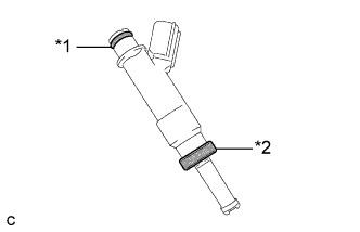
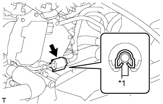
Text in Illustration *1 O-Ring *2 Injector Vibration Insulator Install a new injector vibration insulator to the fuel injector.
-
Apply a light coat of gasoline or spindle oil to the contact surfaces of the O-ring of the fuel injector.
-
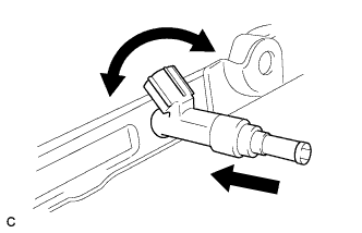
While turning the fuel injector left and right, install it to the fuel delivery pipe.
Note
-
Do not twist the O-ring.
-
After installing the fuel injectors, check that they turn smoothly. If not, replace the O-ring with a new one.
-
-
-
INSTALL FUEL DELIVERY PIPE SUB-ASSEMBLY
-
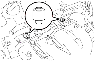
Install the 2 No. 1 delivery pipe spacers to the cylinder head.
Note
Install the No. 1 delivery pipe spacers in the correct direction.
-
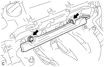
Install the fuel delivery pipe with the 4 fuel injector assemblies, and then temporarily install the 2 bolts.
Note
-
Do not drop the fuel injectors when installing the fuel delivery pipe.
-
Check that the fuel injector assemblies rotate smoothly after installing the fuel delivery pipe.
-
-
Tighten the 2 bolts to the specified torque.
- Torque:
- 21 N*m { 214 kgf*cm, 15 ft.*lbf }
-
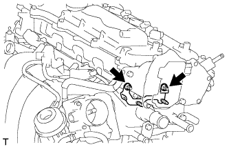
Install the bolt to secure the fuel delivery pipe.
- Torque:
- 21 N*m { 214 kgf*cm, 15 ft.*lbf }
-
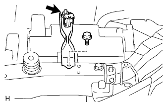
Install the wire harness bracket with the bolt.
- Torque:
- 10 N*m { 102 kgf*cm, 7 ft.*lbf }
-
-
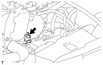
CONNECT FUEL TUBE SUB-ASSEMBLY
-
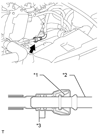
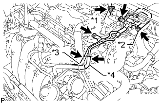
Text in Illustration *1 Retainer *2 Pipe *3 O-Ring Push the fuel tube connector onto the fuel delivery pipe until a "click" sound can be heard.
Note
-
Check that there are no scratches or foreign matter around the contact surfaces of the fuel tube connector and pipe before performing this step.
-
After connecting the fuel tube, check that the fuel tube connector and pipe are securely connected by pulling on them.
-
-
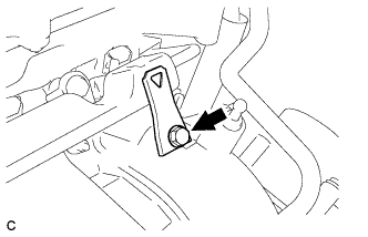
Text in Illustration *1 Claw Install a new No. 2 fuel pipe clamp.
-
-
INSTALL WIRE HARNESS CLAMP BRACKET
-
Install the wire harness clamp bracket with the 2 nuts.
- Torque:
- 18 N*m { 184 kgf*cm, 13 ft.*lbf }
-
-
INSTALL AIR TUBE
-
Install the air tube with the 2 bolts.
- Torque:
- 10 N*m { 102 kgf*cm, 7 ft.*lbf }
-
Connect the No. 2 air hose and No. 1 fuel vapor feed hose.
Text in Illustration *1 Union To Connector Tube Hose *2 Vacuum Hose *3 No. 2 Air Hose *4 No. 1 Fuel Vapor Feed Hose -
Connect the union to connector tube hose and vacuum hose.
-
Connect the fuel vapor feed hose to the purge VSV.
-
-
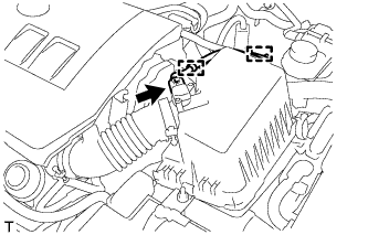
CONNECT ENGINE WIRE
-
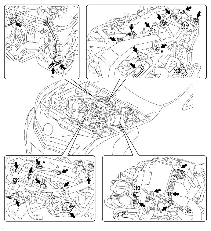
Attach the 10 clamps, and then connect the connectors.
-
Connect the engine wire with the 3 bolts and 2 nuts.
- Torque:
- for bolt A
- 8.4 N*m { 86 kgf*cm, 74 in.*lbf }
- for bolt B
- 10 N*m { 102 kgf*cm, 7 ft.*lbf }
- for nut
- 8.4 N*m { 86 kgf*cm, 74 in.*lbf }
-
-
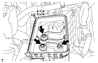
INSTALL BATTERY TRAY
-
INSTALL BATTERY
-
INSTALL BATTERY CLAMP SUB-ASSEMBLY
-
Install the battery clamp with the bolt and nut.
- Torque:
- for bolt
- 17 N*m { 169 kgf*cm, 12 ft.*lbf }
- for nut
- 3.5 N*m { 36 kgf*cm, 31 in.*lbf }
-
Connect the cable to the positive (+) battery terminal.
- Torque:
- 5.4 N*m { 55 kgf*cm, 48 in.*lbf }
-
-
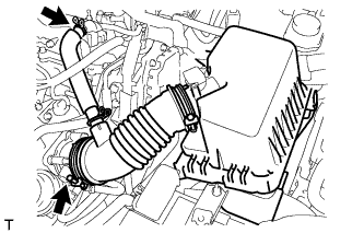
INSTALL AIR CLEANER CASE SUB-ASSEMBLY
-
Install the air cleaner case with the 3 bolts.
- Torque:
- 7.0 N*m { 71 kgf*cm, 62 in.*lbf }
-
Attach the wire harness clamp to the air cleaner case.
-
-
INSTALL AIR CLEANER CAP SUB-ASSEMBLY
-
Connect the air cleaner cap with the band.
-
Connect the PCV hose.
-
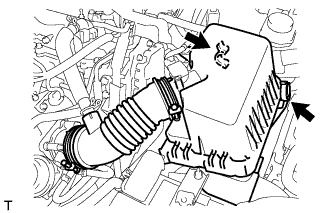
Connect the 2 clamps.
-
Attach the 2 clamps and connect the wire harness.
-
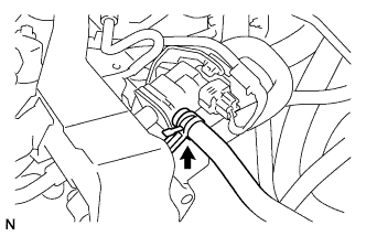
Connect the mass air flow meter connector.
-
-
CONNECT CABLE TO NEGATIVE BATTERY TERMINAL
Note
When disconnecting the cable, some systems need to be initialized after the cable is reconnected Click here.
-
INSPECT FOR FUEL LEAK
-
Make sure that there are no fuel leaks after performing maintenance on the fuel system.
-
Connect the intelligent tester to the DLC3.
-
Turn the ignition switch to ON, and push the intelligent tester main switch on.
Note
Do not start the engine.
-
Enter the following menus: Powertrain / Engine and ECT / Active Test / Control the Fuel Pump / Speed.
-
Check that there are no leaks from the fuel system.
-
Turn the ignition switch off.
-
Disconnect the intelligent tester from the DLC3.
-
-
-
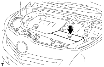
INSTALL NO. 2 CYLINDER HEAD COVER
-
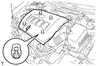
Attach the 4 clips to install the cover.
Note
-
Be sure to attach the clips securely.
-
Do not apply excessive force or hit the cover to attach the clips. This may cause the cover to break.
-
-
-
INSTALL RADIATOR SUPPORT OPENING COVER
-
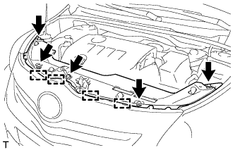
Attach the 4 hooks to install the radiator support opening cover.
-
Install the 5 clips.
-
-
INSTALL BATTERY SERVICE HOLE COVER
-
Install the battery service hole cover with the clip.
-