- Click here
INSTALL FUEL TANK ASSEMBLY
-
Set the fuel tank on a transmission jack.
-
Lift up the transmission jack.
Note:Be careful not to cut the wiring.
-
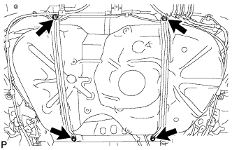
Install the fuel tank and 2 fuel tank bands with the 4 bolts.
39 N*m 400 kgf*cm 29 ft.*lbf
-
-
Click here
CONNECT FUEL HOSE
-
Connect the No. 1 charcoal canister outlet hose.
-
Connect the fuel tank vent hose as shown in the illustration.
Note:Be sure to tighten the hose clamp so that it is at the correct angle.
-
Connect the fuel tank to filler pipe hose as shown in the illustration.
Note:Be sure to tighten the hose clamp so that it is at the correct angle.
-
- Click here
CONNECT FUEL TANK MAIN TUBE SUB-ASSEMBLY
-
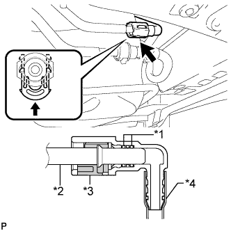
Connect the fuel tank main tube.
Table 1. Text in Illustration *1 O-Ring *2 Fuel Pipe *3 Retainer *4 Nylon Tube Tip:Push the parts together firmly until a "click" sound is heard.
Note:
-
Before installing the tube connectors to the pipes, check if there is any damage or foreign matter in the connectors.
-
After the connection, check if the connectors and pipes are securely connected by trying to pull them apart.
-
-
- Click here
CONNECT NO. 1 FUEL EVAPORATION TUBE SUB-ASSEMBLY
-
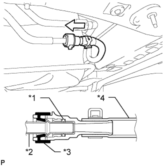
Push the tube connector onto the fuel pipe and install the retainer.
Table 2. Text in Illustration *1 O-Ring *2 Fuel Pipe *3 Retainer *4 Nylon Tube Note:
-
Check if there is any damage or foreign objects on the connection part of the fuel pipe.
-
After connecting, check if the fuel pipe and connector are securely connected by pulling on them.
-
-
- Click here
CONNECT PARKING BRAKE CABLE
-
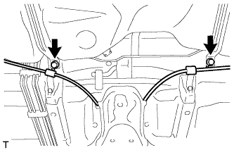
Connect the parking brake cable with the 2 bolts.
6.0 N*m 61 kgf*cm 53 in.*lbf
-
- Click here
INSTALL NO. 1 FUEL TANK PROTECTOR
-
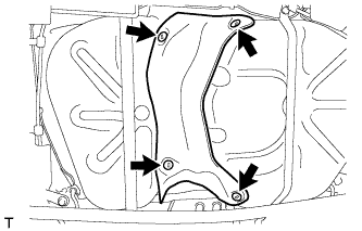
Install the No. 1 fuel tank protector with the 4 clips.
-
- Click here
INSTALL REAR FLOOR SIDE MEMBER BRACE SUB-ASSEMBLY
-
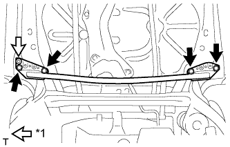
Install the rear floor side member brace with the clip and 4 bolts.
54 N*m 551 kgf*cm 40 ft.*lbf Table 3. Text in Illustration *1 Clip
-
- Click here
INSTALL REAR FLOOR SIDE MEMBER COVER RH
-
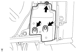
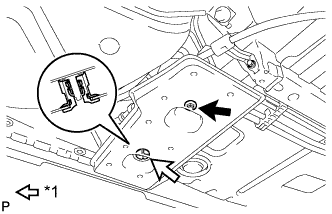
Install the rear floor side member cover with the nut and 2 bolts.
-
- Click here
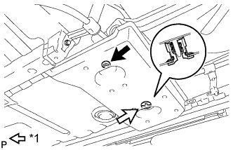
INSTALL REAR FLOOR SIDE MEMBER COVER LH
-
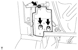
Install the rear floor side member cover with the nut and 2 bolts.
-
- Click here
INSTALL FRONT FLOOR CENTER COVER LH
-
Install the front floor center cover with the nut and grommet.
Table 4. Text in Illustration *1 Grommet
-
- Click here
INSTALL FRONT FLOOR CENTER COVER RH
-
Install the front floor center cover with the nut and grommet.
Table 5. Text in Illustration *1 Grommet
-
- Click here
INSTALL EXHAUST PIPE ASSEMBLY
-
Install the exhaust pipe (Click here).
-
- Click here
CONNECT FUEL PUMP CONNECTOR
-
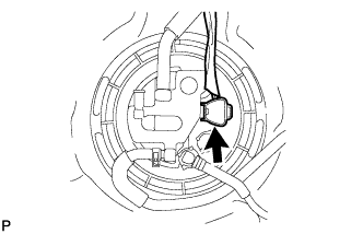
Connect the fuel pump connector.
-
- Click here
ADD FUEL
- Click here
INSTALL FUEL TANK CAP ASSEMBLY
- Click here
CONNECT CABLE TO NEGATIVE BATTERY TERMINAL
Note:When disconnecting the cable, some systems need to be initialized after the cable is reconnected (Click here).
- Click here
INSPECT FUEL LEAK
-
Make sure that there are no fuel leaks after performing maintenance on the fuel system.
-
Connect the intelligent tester to the DLC3.
-
Turn the ignition switch to ON, and push the intelligent tester main switch on.
Note:Do not start the engine.
-
Enter the following menus: Powertrain / Engine and ECT / Active Test / Control the Fuel Pump / Speed.
-
Check that there are no leaks from the fuel system.
-
Turn the ignition switch off.
-
Disconnect the intelligent tester from the DLC3.
-
-
- Click here
INSTALL REAR FLOOR SERVICE HOLE COVER
-
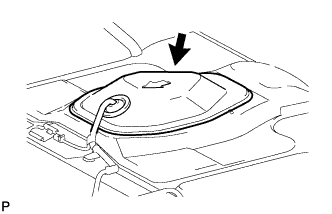
Install the rear floor service hole cover with new butyl tape.
-
- Click here
INSTALL REAR CENTER SEAT ASSEMBLY (w/ REAR CENTER SEAT ASSEMBLY)
-
Install the rear center seat (Click here).
-
- Click here
INSTALL REAR NO. 1 SEAT ASSEMBLY (w/ REAR NO. 1 SEAT ASSEMBLY)
-
Install the rear No. 1 seat (Click here).
-