FUEL TANK REASSEMBLY

-
INSTALL NO. 1 CHARCOAL CANISTER OUTLET HOSE
-
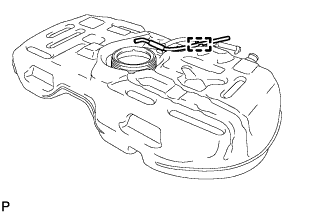
Attach the clamp to install the No. 1 charcoal canister outlet hose.
-
-
INSTALL NO. 1 FUEL EVAPORATION TUBE SUB-ASSEMBLY
-
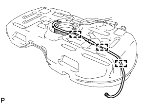
Attach the 3 clamps to install the No. 1 fuel evaporation tube.
-
-
INSTALL FUEL TANK MAIN TUBE SUB-ASSEMBLY
-
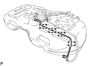
Attach the 4 clamps to install the fuel tank main tube.
-
-
INSTALL NO. 2 FUEL TANK CUSHION
-
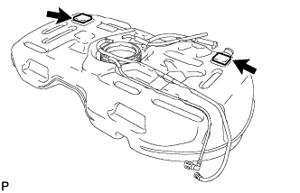
Install the 2 cushions.
-
-
INSTALL NO. 1 FUEL TANK CUSHION
-
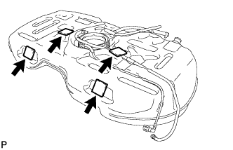
Install the 4 cushions.
-
-
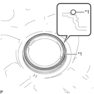
INSPECT FUEL PUMP GAUGE RETAINER
-
Inspect the fuel pump gauge retainer.
-
Install the fuel pump gauge retainer to the fuel tank by hand with the fuel suction with pump disconnected.
-
If the fuel pump gauge retainer can be turned 180° or more by hand, reuse the retainer.
-
If the fuel pump gauge retainer cannot be turned 180° or more by hand, replace it with a new one.
Tech Tips
Check that there is no damage, dents, foreign matter, or other defects on the threads of the fuel tank.
-
-
-
-
INSTALL FUEL SUCTION WITH PUMP ASSEMBLY
-
Text in Illustration *1 New Gasket Install a new gasket onto the fuel tank.
-
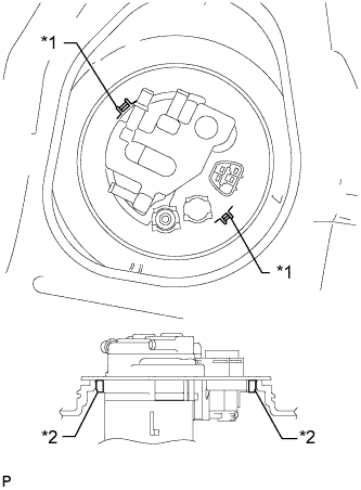
Text in Illustration *1 Notch *2 Protrusion Set the fuel suction with pump to the fuel tank.
Note
Make sure that the fuel sender gauge arm does not bend.
-
Align the protrusion of the fuel suction with pump with the notch of the fuel tank.
-
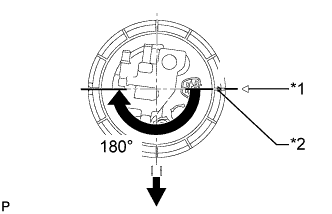
Text in Illustration *1 Start Mark
(Fuel Tank Side)
*2 Start Mark
(Fuel Pump Gauge Retainer Side)

Front Side of Vehicle While holding the fuel suction with pump and gauge tube by hand to prevent it from tilting, align the start marks on a new fuel pump gauge retainer and fuel tank and tighten the fuel pump gauge retainer 180° by hand.
Tech Tips
Check that there is no damage, dents, foreign matter, or other defects on the threads of the fuel tank.
-
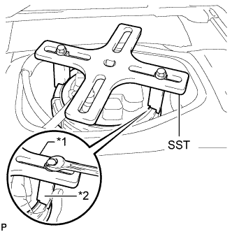
Text in Illustration *1 SST (Plate) *2 SST (Claw) Temporarily install SST (plate and 2 claws) to the fuel pump gauge retainer.
- SST
- 09808-14030
Tech Tips
-
Be sure to use 2 SST (claws) as shown in the illustration.
-
Engage SST (claws) securely with the fuel pump gauge retainer ribs to secure SST.
-
While securely pressing SST (claws) against the fuel pump gauge retainer ribs, install the 2 bolts.
Tech Tips
Install SST while pressing SST (claws) against the fuel pump gauge retainer (towards the center of SST).
-
Install SST (handle).
-
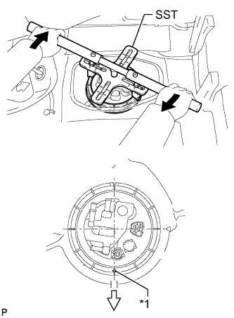
Text in Illustration *1 Start Mark
(Fuel Pump Gauge Retainer Side)
Turn 
Front Side of Vehicle Tighten the fuel pump gauge retainer approximately 270° so that the start mark on the fuel pump gauge retainer is in the position shown in the illustration.
- SST
- 09808-14030
Note
-
Do not use any tools other than those specified in this operation. Damage to the fuel pump gauge retainer or fuel tank may result.
-
Do not press down on SST excessively as this may make the fuel pump gauge retainer hard to rotate, and may damage components.
-
Make sure to rotate SST (handle) horizontally. If SST (handle) is rotated at an angle, SST may come off.
-
Do not spin SST too fast or use an impact wrench as this may result in damage to components.
-
If SST comes off of the fuel pump gauge retainer, loosen SST (bolts) and reinstall SST.
Tech Tips
-
Lightly press down on SST to prevent it from separating from the fuel pump gauge retainer. While pressing SST, rotate the handle slowly to tighten the fuel pump gauge retainer.
-
The tips of SST (claws) can be fitted onto the ribs of the fuel pump gauge retainer.
-