Perform "Inspection After Repairs" after replacing the fuel pump (Click here).
- Click here
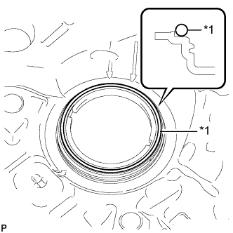
INSPECT FITTING OF FUEL PUMP GAUGE RETAINER
-
Inspect the fuel pump gauge retainer.
-
Install the fuel pump gauge retainer to the fuel tank by hand with the fuel suction with pump disconnected.
-
If the fuel pump gauge retainer can be turned 180° or more by hand, reuse the retainer.
-
If the fuel pump gauge retainer cannot be turned 180° or more by hand, replace it with a new one.
Tip:Check that there is no damage, dents, foreign matter, or other defects on the threads of the fuel tank.
-
-
-
- Click here
INSTALL FUEL SUCTION WITH PUMP ASSEMBLY
-
Install a new gasket onto the fuel tank.
Table 1. Text in Illustration *1 New Gasket -
Set the fuel suction with pump to the fuel tank.
Note:Make sure that the fuel sender gauge arm does not bend.
-
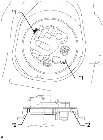
Align the protrusion of the fuel suction with pump with the notch of the fuel tank.
Table 2. Text in Illustration *1 Notch *2 Protrusion -
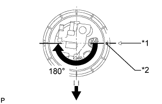
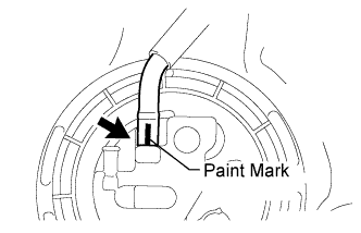
While holding the fuel suction with pump and gauge tube by hand to prevent it from tilting, align the start marks on a new fuel pump gauge retainer and fuel tank and tighten the fuel pump gauge retainer 180° by hand.
Table 3. Text in Illustration *1 Start Mark
(Fuel Tank Side)
*2 Start Mark
(Fuel Pump Gauge Retainer Side)

Front Side of Vehicle Tip:Check that there is no damage, dents, foreign matter, or other defects on the threads of the fuel tank.
-
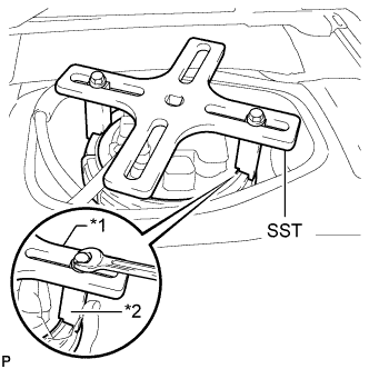
Temporarily install SST (plate and 2 claws) to the fuel pump gauge retainer.
09808-14030 Table 4. Text in Illustration *1 SST (Plate) *2 SST (Claw) Tip:
-
Be sure to use 2 SST (claws) as shown in the illustration.
-
Engage SST (claws) securely with the fuel pump gauge retainer ribs to secure SST.
-
-
While securely pressing SST (claws) against the fuel pump gauge retainer ribs, install the 2 bolts.
Tip:Install SST while pressing SST (claws) against the fuel pump gauge retainer (towards the center of SST).
-
Install SST (handle).
-
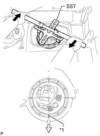
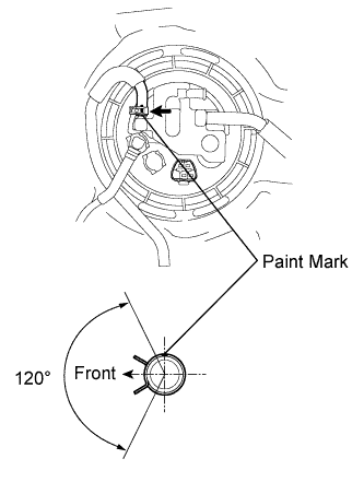
Tighten the fuel pump gauge retainer approximately 270° so that the start mark on the fuel pump gauge retainer is in the position shown in the illustration.
09808-14030 Table 5. Text in Illustration *1 Start Mark
(Fuel Pump Gauge Retainer Side)
Turn 
Front Side of Vehicle Note:
-
Do not use any tools other than those specified in this operation. Damage to the fuel pump gauge retainer or fuel tank may result.
-
Do not press down on SST excessively as this may make the fuel pump gauge retainer hard to rotate, and may damage components.
-
Make sure to rotate SST (handle) horizontally. If SST (handle) is rotated at an angle, SST may come off.
-
Do not spin SST too fast or use an impact wrench as this may result in damage to components.
-
If SST comes off of the fuel pump gauge retainer, loosen SST (bolts) and reinstall SST.
Tip:
-
Lightly press down on SST to prevent it from separating from the fuel pump gauge retainer. While pressing SST, rotate the handle slowly to tighten the fuel pump gauge retainer.
-
The tips of SST (claws) can be fitted onto the ribs of the fuel pump gauge retainer.
-
-
- Click here
CONNECT NO. 1 CHARCOAL CANISTER OUTLET HOSE
-
Connect the No. 1 charcoal canister outlet hose to the fuel suction with pump.
-
- Click here
CONNECT NO. 1 FUEL EVAPORATION TUBE SUB-ASSEMBLY
-
Connect the No. 1 fuel evaporation tube to the fuel suction with pump with the clip.
-
- Click here
CONNECT FUEL TANK MAIN TUBE SUB-ASSEMBLY
-
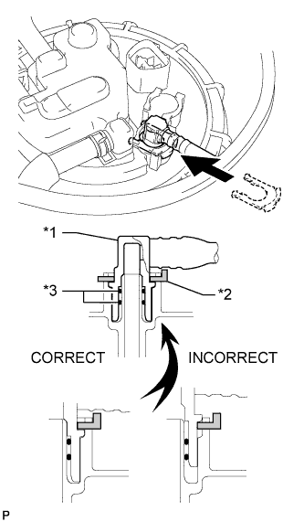
Push the fuel tube joint into the plug of the fuel suction with pump, and then install the tube joint clip.
Table 6. Text in Illustration *1 Fuel Tube Joint *2 Tube Joint Clip *3 O-Ring Note:
-
Check that there are no scratches or foreign objects around the connected part of the fuel tube joint and plug before performing this work.
-
Check that the fuel tube joint is securely and fully inserted.
-
Check that the tube joint clip is on the collar of the fuel tube joint.
-
After installing the tube joint clip, check that the fuel tank main tube cannot be pulled out.
-
-
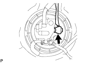
Connect the fuel pump connector.
-
- Click here
CONNECT CABLE TO NEGATIVE BATTERY TERMINAL
Note:When disconnecting the cable, some systems need to be initialized after the cable is reconnected (Click here).
- Click here
INSPECT FOR FUEL LEAK
-
Make sure that there are no fuel leaks after performing maintenance on the fuel system.
-
Connect the intelligent tester to the DLC3.
-
Turn the ignition switch to ON, and push the intelligent tester main switch on.
Note:Do not start the engine.
-
Enter the following menus: Powertrain / Engine and ECT / Active Test / Control the Fuel Pump / Speed.
-
Check that there are no leaks from the fuel system.
-
Turn the ignition switch off.
-
Disconnect the intelligent tester from the DLC3.
-
-
- Click here
INSTALL REAR FLOOR SERVICE HOLE COVER
-
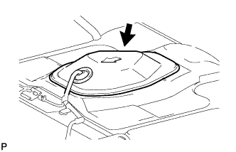
Install the rear floor service hole cover with new butyl tape.
-
- Click here
INSTALL REAR CENTER SEAT ASSEMBLY (w/ REAR NO. 1 SEAT)
-
Install the center seat (Click here).
-
- Click here
INSTALL REAR NO. 1 SEAT ASSEMBLY (w/ REAR NO. 1 SEAT)
-
Install the rear No. 1 seat (Click here).
-