FUEL INJECTOR REMOVAL

-
DISCHARGE FUEL SYSTEM PRESSURE
-
Discharge fuel system pressure Click here.
-
-
REMOVE BATTERY SERVICE HOLE COVER
-
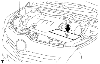
Remove the clip and battery service hole cover.
-
-
REMOVE RADIATOR SUPPORT OPENING COVER
-
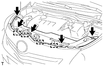
Remove the 5 clips.
-
Detach the 4 hooks and remove the radiator support opening cover.
-
-
PRECAUTION
Note
After turning the ignition switch off, waiting time may be required before disconnecting the cable from the battery terminal. Therefore, make sure to read the disconnecting the cable from the battery terminal notice before proceeding with work Click here.
-
DISCONNECT CABLE FROM NEGATIVE BATTERY TERMINAL
Note
When disconnecting the cable, some systems need to be initialized after the cable is reconnected Click here.
-
REMOVE NO. 2 CYLINDER HEAD COVER
-
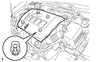
Hold the rear of the cover and raise it to detach the 2 clips on the rear of the cover. Continue to raise the cover to detach the 2 clips on the front of the cover and remove the cover.
Note
Attempting to detach both front and rear clips at the same time may cause the cover to break.
-
-
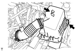
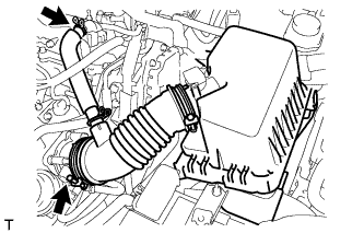
REMOVE AIR CLEANER CAP SUB-ASSEMBLY
-
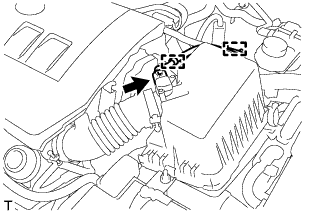
Disconnect the mass air flow meter connector.
-
Detach the 2 clamps and disconnect the wire harness.
-
Disconnect the 2 clamps.
-
Disconnect the PCV hose.
-
Loosen the band and remove the air cleaner cap.
-
-
REMOVE AIR CLEANER CASE SUB-ASSEMBLY
-
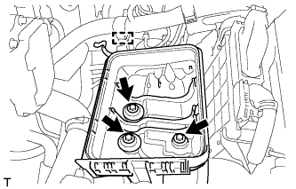
Detach the wire harness clamp from the air cleaner case.
-
Remove the 3 bolts and air cleaner case.
-
-
REMOVE BATTERY CLAMP SUB-ASSEMBLY
-
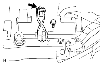
Disconnect the cable from the positive (+) battery terminal.
-
Remove the bolt and loosen the nut.
-
Remove the battery clamp.
-
-
REMOVE BATTERY
-
REMOVE BATTERY TRAY
-
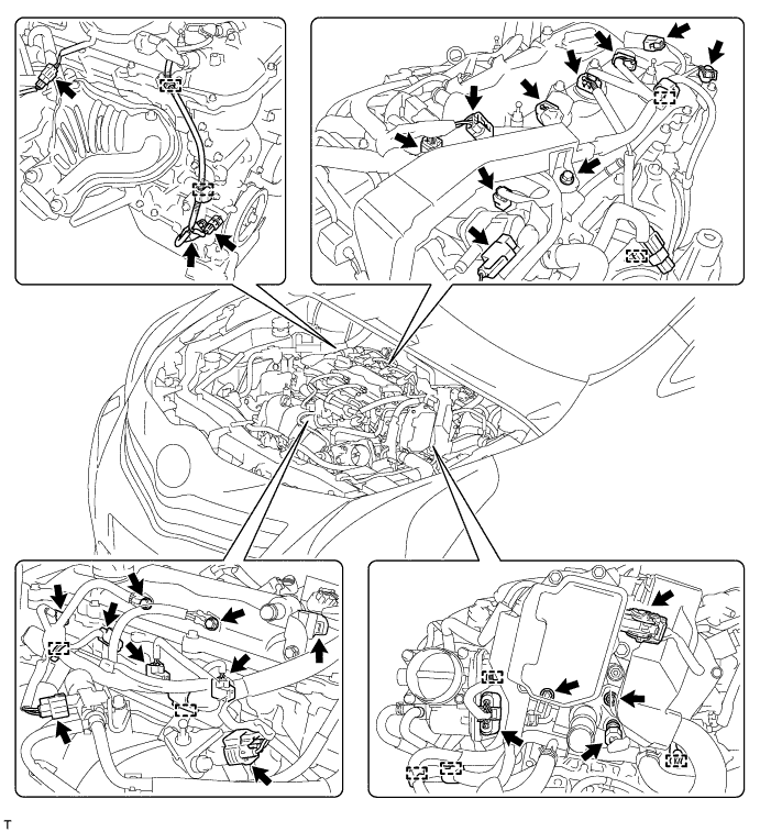
DISCONNECT ENGINE WIRE
-
Detach the 10 clamps, and then disconnect the connectors.
-
Remove the 3 bolts and 2 nuts, and then disconnect the engine wire.
-
-
REMOVE AIR TUBE
-
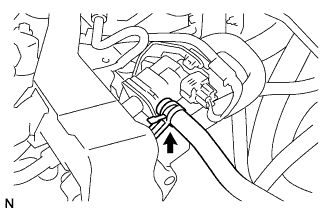
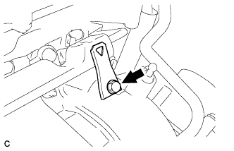
Disconnect the fuel vapor feed hose from the purge VSV.
-
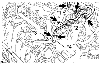
Text in Illustration *1 Union To Connector Tube Hose *2 Vacuum Hose *3 No. 2 Air Hose *4 No. 1 Fuel Vapor Feed Hose Disconnect the union to connector tube hose and vacuum hose.
-
Disconnect the No. 2 air hose and No. 1 fuel vapor feed hose.
-
Remove the 2 bolts and air tube.
-
-
REMOVE WIRE HARNESS CLAMP BRACKET
-
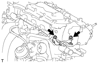
Remove the 2 nuts and wire harness clamp bracket.
-
-
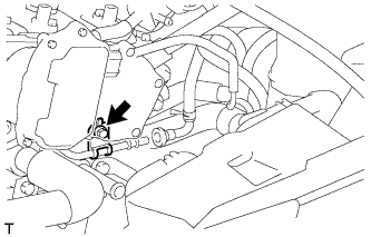
DISCONNECT FUEL TUBE SUB-ASSEMBLY
-
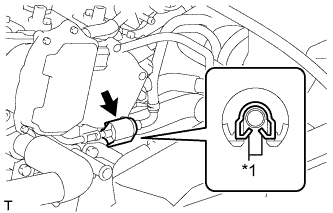
Text in Illustration *1 Claw Remove the No. 2 fuel pipe clamp.
-
Wipe off any dirt on the fuel tube connector.
-
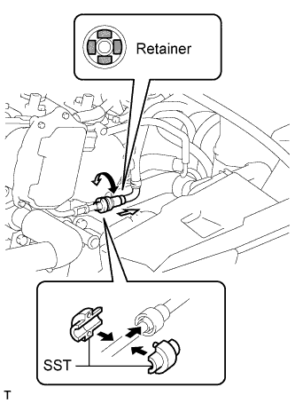
Hold the fuel tube connector and install SST.
- SST
- 09268-21010
-
Turn SST to align the retainer inside the fuel tube connector with the chamfered part of SST.
-
Insert SST into the fuel tube and hold it. Then push the fuel tube connector toward SST.
-
Mount the retainer of the fuel tube connector onto the chamfered part of SST.
-
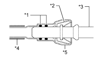
Text in Illustration *1 O-Ring *2 Retainer *3 Pipe *4 Nylon Tube *5 Fuel Tube Connector Slide SST and the fuel tube connector together towards the fuel tube until they make a "click" sound, and then disconnect the fuel tube.
-
Drain the fuel remaining inside the fuel tube.
-
Cover the fuel tube and fuel pipe with a plastic bag to protect the disconnected parts.
-
-
REMOVE FUEL DELIVERY PIPE SUB-ASSEMBLY
-
Remove the bolt and wire harness bracket.
-
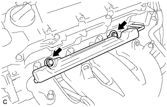
Remove the 2 bolts.
-
Remove the bolt and the fuel delivery pipe.
-
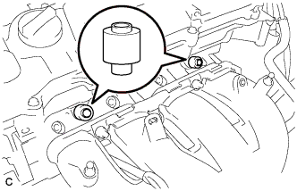
Remove the 2 No. 1 delivery pipe spacers.
-
-
REMOVE FUEL INJECTOR ASSEMBLY
-
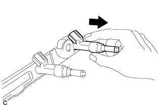
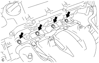
Pull the 4 fuel injector assemblies out of the fuel delivery pipe.
-
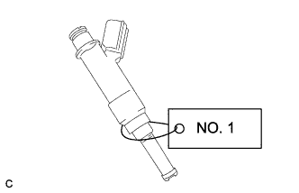
For reinstallation, attach a tag or label to the injector shaft.
Note
Prevent entry of foreign objects by covering the fuel injector with plastic bags.
-
Remove the 4 injector vibration insulators.
-