FUEL TANK INSTALLATION

-
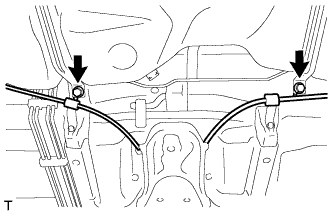
INSTALL FUEL TANK RETURN TUBE SUB-ASSEMBLY
-
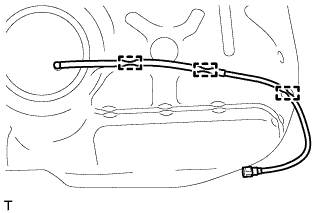
Attach the fuel tank return tube to the 3 clamps to install it.
-
-
INSTALL FUEL TANK MAIN TUBE SUB-ASSEMBLY
-
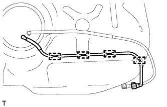
Attach the fuel tank main tube to the 4 clamps to install it.
-
-
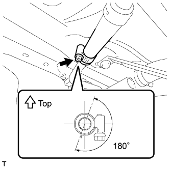
INSTALL FUEL TANK TO FILLER PIPE HOSE
-
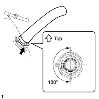
Install the filler pipe hose to the fuel tank and tighten the hose clamp bolt so that the clamp is as shown in the illustration.
Note
Be sure to tighten the hose clamp so that it is at the correct angle.
Tech Tips
From the position in the illustration, the hose clamp can also be positioned so that the hose clamp bolt is on the opposite side of the hose with the bolt tip facing upwards.
-
-
INSTALL NO. 2 FUEL TANK CUSHION
-
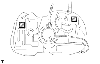
Install 2 new No. 2 fuel tank cushions at the locations shown in the illustration.
-
-
INSTALL NO. 1 FUEL TANK CUSHION
-
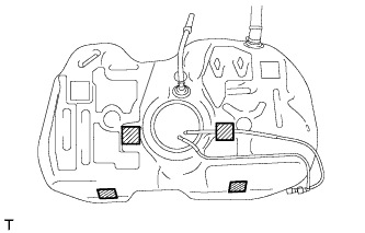
Install 4 new No. 1 fuel tank cushions at the locations shown in the illustration.
-
-
INSTALL FUEL TANK ASSEMBLY
-
Using a transmission jack, support the fuel tank.
-
Raise the transmission jack and install the fuel tank to the vehicle.
Note
-
Do not drop the fuel tank.
-
When installing the fuel tank, tilt it slightly to prevent it from interfering with the suspension arm or other surrounding parts.
-
-
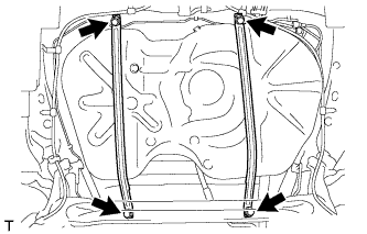
Install the 2 fuel tank bands with the 4 bolts.
- Torque:
- 39 N*m { 398 kgf*cm, 29 ft.*lbf }
-
Connect the fuel tank main tube.
-
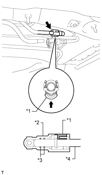
Text in Illustration *1 Retainer *2 Fuel Tube Connector *3 O-Ring *4 Pipe Align the fuel tube connector with the pipe, push the fuel tube connector in until it comes into contact with the seat to connect the fuel tank main tube to the pipe, and then push the retainer up until the claws lock.
Note
-
Check that there are no scratches or foreign objects around the connecting part of the fuel tube connector and pipe before starting this step.
-
After connecting the fuel tank main tube, check that the fuel tank main tube is securely connected by pulling on the fuel tube connector.
-
-
-
Connect the fuel tank return tube.
-
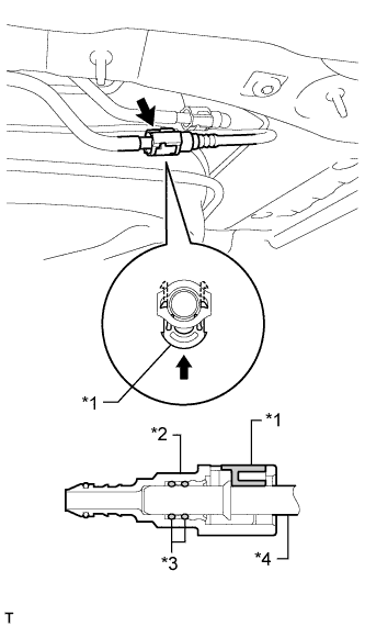
Text in Illustration *1 Retainer *2 Fuel Tube Connector *3 O-Ring *4 Pipe Align the fuel tube connector with the pipe, push the fuel tube connector in until it comes into contact with the seat to connect the fuel tank return tube to the pipe, and then push the retainer up until the claws lock.
Note
-
Check that there are no scratches or foreign objects around the connecting part of the fuel tube connector and pipe before starting this step.
-
After connecting the fuel tank return tube, check that the fuel tank return tube is securely connected by pulling on the fuel tube connector.
-
-
-
Connect the parking brake cable with the 2 bolts.
- Torque:
- 6.0 N*m { 61 kgf*cm, 53 in.*lbf }
-
Connect the breather hose to the fuel tank filler pipe and tighten the hose clamp bolt so that the clamp is as shown in the illustration.
Note
Be sure to tighten the hose clamp so that it is at the correct angle.
-
-
CONNECT FUEL TANK TO FILLER PIPE HOSE
-
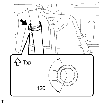
Connect the filler pipe hose to the fuel tank filler pipe and tighten the hose clamp bolt so that the clamp is as shown in the illustration.
Note
Be sure to tighten the hose clamp so that it is at the correct angle.
-
-
INSTALL NO. 1 FUEL TANK PROTECTOR
-
Install the fuel tank protector cushion.
-
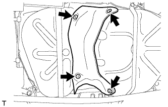
Install the No. 1 fuel tank protector with the 4 clips.
-
-
INSTALL REAR FLOOR SIDE MEMBER BRACE SUB-ASSEMBLY
-
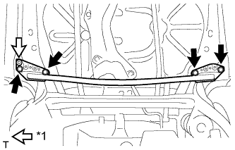
Text in Illustration *1 Clip Attach the clip and install the rear floor side member brace with the 4 bolts.
- Torque:
- 54 N*m { 551 kgf*cm, 40 ft.*lbf }
-
-
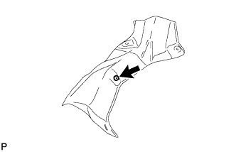
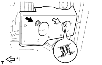
INSTALL REAR FLOOR SIDE MEMBER COVER LH
-
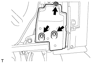
Install the rear floor side member cover with the nut and 2 bolts.
-
-
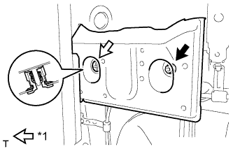
INSTALL REAR FLOOR SIDE MEMBER COVER RH
-
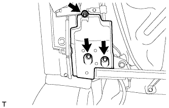
Install the rear floor side member cover with the nut and 2 bolts.
-
-
INSTALL FRONT FLOOR CENTER COVER LH
-
Text in Illustration *1 Grommet Attach the grommet and install the front floor center cover with the nut.
-
-
INSTALL FRONT FLOOR CENTER COVER RH
-
Text in Illustration *1 Grommet Attach the grommet and install the front floor center cover with the nut.
-
-
ADD FUEL
-
INSTALL FUEL TANK VENT TUBE SUB-ASSEMBLY
-
Text in Illustration *1 New Gasket Apply a light coat of diesel fuel to a new gasket and install the gasket to the fuel tank.
-
Install the fuel tank vent tube to the fuel tank.
Note
Make sure that the fuel sender gauge arm does not bend.
-
Text in Illustration *1 Notch *2 Protrusion Align the protrusions of the fuel tank vent tube with the notches of the fuel tank.
-
-
INSTALL FUEL PUMP GAUGE RETAINER
-
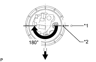
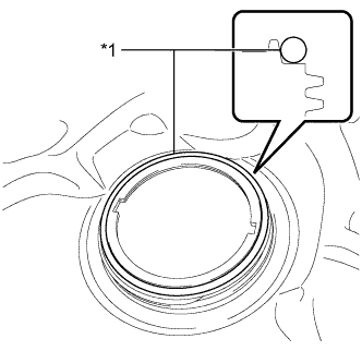
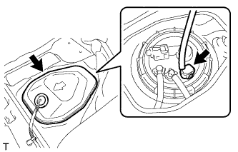
Text in Illustration *1 Start Mark
(Fuel Tank Side)
*2 Start Mark
(Fuel Pump Gauge Retainer Side)

Front Side of Vehicle While holding the fuel suction with pump and gauge tube by hand to prevent it from tilting, align the start marks on a new fuel pump gauge retainer and fuel tank and tighten the fuel pump gauge retainer 180° by hand.
Tech Tips
Check that there is no damage, dents, foreign matter, or other defects on the threads of the fuel tank.
-
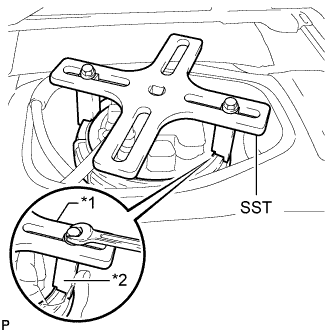
Text in Illustration *1 SST (Plate) *2 SST (Claw) Temporarily install SST (plate and 2 claws) to the fuel pump gauge retainer.
- SST
- 09808-14030
Tech Tips
-
Be sure to use 2 SST (claws) as shown in the illustration.
-
Engage SST (claws) securely with the fuel pump gauge retainer ribs to secure SST.
-
While securely pressing SST (claws) against the fuel pump gauge retainer ribs, install the 2 bolts.
Tech Tips
Install SST while pressing SST (claws) against the fuel pump gauge retainer (towards the center of SST).
-
Install SST (handle).
-
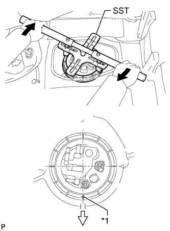
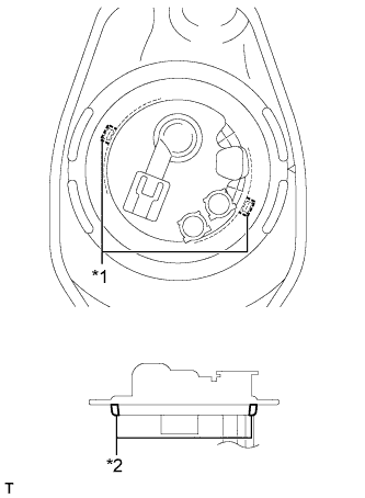
Text in Illustration *1 Start Mark
(Fuel Pump Gauge Retainer Side)
Turn 
Front Side of Vehicle Tighten the fuel pump gauge retainer approximately 270° so that the start mark on the fuel pump gauge retainer is in the position shown in the illustration.
- SST
- 09808-14030
Note
-
Do not use any tools other than those specified in this operation. Damage to the fuel pump gauge retainer or fuel tank may result.
-
Do not press down on SST excessively as this may make the fuel pump gauge retainer hard to rotate, and may damage components.
-
Make sure to rotate SST (handle) horizontally. If SST (handle) is rotated at an angle, SST may come off.
-
Do not spin SST too fast or use an impact wrench as this may result in damage to components.
-
If SST comes off of the fuel pump gauge retainer, loosen SST (bolts) and reinstall SST.
Tech Tips
-
Lightly press down on SST to prevent it from separating from the fuel pump gauge retainer. While pressing SST, rotate the handle slowly to tighten the fuel pump gauge retainer.
-
The tips of SST (claws) can be fitted onto the ribs of the fuel pump gauge retainer.
-
-
CONNECT FUEL TANK RETURN TUBE SUB-ASSEMBLY
-
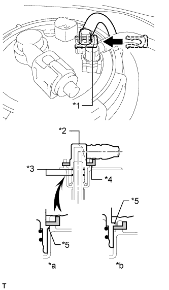
Text in Illustration *1 Tube Joint Clip *2 Fuel Tube Joint *3 O-Ring *4 Tube Joint Clip *5 Collar *a CORRECT *b INCORRECT Push the fuel tube joint into the plug of the fuel tank vent tube, and then install the tube joint clip.
Note
-
Check that there are no scratches or foreign objects on the connecting parts.
-
Check that the fuel tube joint is inserted securely.
-
Check that the tube joint clip is on the collar of the fuel tube joint.
-
After installing the tube joint clip, check that the fuel tube joint cannot be pulled off.
-
-
-
CONNECT FUEL TANK MAIN TUBE SUB-ASSEMBLY
-
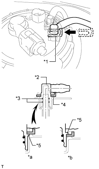
Text in Illustration *1 Tube Joint Clip *2 Fuel Tube Joint *3 O-Ring *4 Tube Joint Clip *5 Collar *a CORRECT *b INCORRECT Push the fuel tube joint into the plug of the fuel tank vent tube, and then install the tube joint clip.
Note
-
Check that there are no scratches or foreign objects on the connecting parts.
-
Check that the fuel tube joint is inserted securely.
-
Check that the tube joint clip is on the collar of the fuel tube joint.
-
After installing the tube joint clip, check that the fuel tube joint cannot be pulled off.
-
-
-
INSTALL REAR FLOOR SERVICE HOLE COVER
-
Connect the sender gauge connector.
-
Install the rear floor service hole cover with new butyl tape.
Note
Be careful that the rear floor service hole cover does not overlap the protrusions of the floor panel when installing.
-
-
BLEED AIR FROM FUEL SYSTEM
-
Using the hand pump mounted on the fuel filter cap, bleed the air from the fuel system. Continue pumping until the pump resistance increases.
Note
-
Hand pump pumping speed: Max. 2 strokes/ sec.
-
The hand pump must be pushed with a full stroke during pumping.
-
When the fuel pressure at the supply pump inlet port reaches a saturated pressure, the hand pump resistance increases.
-
If pumping is interrupted during the air bleeding process, fuel in the fuel line may return to the fuel tank. Continue pumping until the hand pump resistance increases.
-
If the hand pump resistance does not increase despite consecutively pumping 200 times or more, there may be a fuel leak between the fuel tank and fuel filter, the hand pump may be malfunctioning, or the vehicle may have run out of fuel.
-
If air bleeding using the hand pump is incomplete, the common rail pressure does not rise to the pressure range necessary for normal use, and the engine cannot be started.
-
-
Start the engine.
Note
-
Even if air bleeding using the hand pump has been completed, the starter may need to be cranked for 10 seconds or more to start the engine.
-
Do not crank the engine continuously for more than 20 seconds. The battery may be discharged.
-
Use a fully-charged battery.
-
When the engine can be started, proceed to the next step.
-
If the engine cannot be started, bleed the air again using the hand pump until the hand pump resistance increases (refer to the procedures above). Then start the engine.
-
-
Turn the ignition switch off.
-
Connect the intelligent tester to the DLC3.
-
Turn the ignition switch to ON and turn the intelligent tester on.
-
Clear the DTCs.
-
for DPF: Click here
-
for CCo: Click here
-
-
Start the engine.*1
-
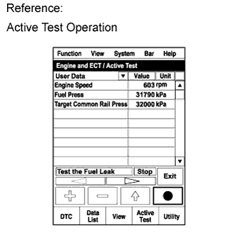
Enter the following menus: Powertrain / Engine and ECT / Active Test / Test the Fuel Leak.*2
-
Perform the following test 5 times with on/off intervals of 10 seconds: Active Test / Test the Fuel Leak.*3
-
Allow the engine to idle for 3 minutes or more after performing the Active Test for the fifth time.
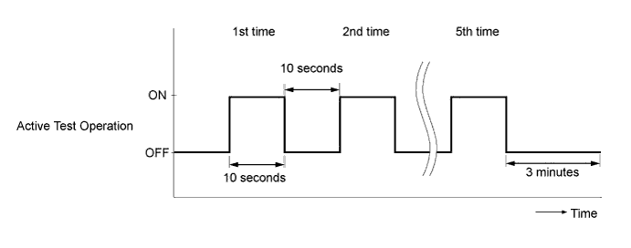
Tech Tips
When the Active Test "Test the Fuel Leak" is used to change the pump control mode, the actual fuel pressure inside the common rail drops below the target fuel pressure when the Active Test is off, but this is normal and does not indicate a pump malfunction.
-
Enter the following menus: Powertrain / Engine and ECT / DTC.
-
Read Current DTCs.
-
When no DTCs are output, the air bleeding is completed.
-
If any DTCs are output, proceed to the next step.
-
-
Clear the DTCs.
-
for DPF: Click here
-
for CCo: Click here
-
-
Repeat steps *1 to *3.
-
Enter the following menus: Powertrain / Engine and ECT / DTC.
-
Read Current DTCs.
OK No DTCs are output.
-
-
INSPECT FOR FUEL LEAK
Tech Tips
Using the intelligent tester to perform Active Tests allow relays, VSVs, actuators and other items to be operated without removing any parts. This non-intrusive functional inspection can be very useful because intermittent operation may be discovered before parts or wiring is disturbed. Performing Active Tests early in troubleshooting is one way to save diagnostic time. Data List information can be displayed while performing Active Tests.
-
Perform Active Test.
-
Connect the intelligent tester to the DLC3.
-
Turn the ignition switch to ON.
-
Start the engine.
-
Turn the intelligent tester on.
-
Enter the following menus: Powertrain / Engine / Active Test.
-
Perform the Active Test.
Tester Display Test Part Control Range Diagnostic Notes Test the Fuel Leak Pressurizes common rail internal fuel pressure, and checks for fuel leaks Stop/Start Performs inspection of the high pressure fuel system.
-
Engine Speed: 2050 rpm
-
Fuel Pressure: 172000 kPa
-
Target Common Rail Pressure: 176000 kPa
-
Target Pump SCV Current: 1400 mA
-
MAP: 176 kPa
-
MAF: 39 g/sec.
-
-
-
-
INSTALL REAR CENTER SEAT ASSEMBLY (w/ Rear No. 1 Seat)
-
Install the rear center seat assembly Click here.
-
-
INSTALL REAR NO. 1 SEAT ASSEMBLY (w/ Rear No. 1 Seat)
-
Install the rear No. 1 seat assembly Click here.
-
-
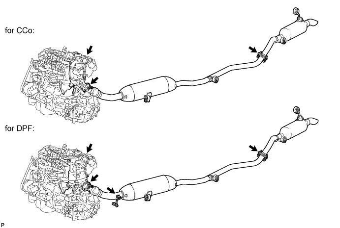
INSTALL EXHAUST PIPE ASSEMBLY
-
Install the exhaust pipe assembly Click here.
-
-
INSPECT FOR EXHAUST GAS LEAK
-
Check that there are no exhaust gas leaks from the points (connection areas of the exhaust pipes and installation areas of each sensor) shown in the illustration.
-