ENGINE UNIT REMOVAL

Note
-
After the engine has stopped, wait at least 1 minute before releasing the high pressure lines.
-
When working on the fuel circuit, protect the generator assembly against dirt contamination. Cover generator assembly with suitable materials. Failure to comply with this procedure may result in a generator assembly malfunction.
-
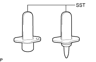
After disconnecting the pressure line, it is absolutely essential to seal the injector assemblies and the common rail assembly with SST.
SST PZ4TB-04941-79
-
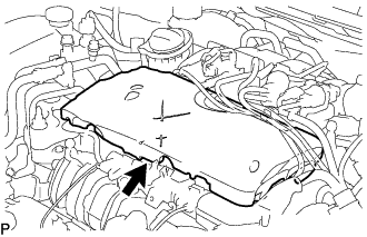
REMOVE ENGINE COVER
-
DISCONNECT ENGINE WIRE
-
REMOVE FAN AND GENERATOR V BELT
-
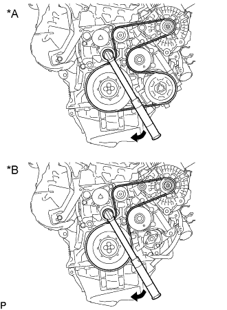
Text in Illustration *A w/ Air Conditioning System *B w/o Air Conditioning System Rotate the pulley of the V-ribbed belt tensioner assembly clockwise to loosen the fan and generator V belt and reduce the tension. Then remove the fan and generator V belt.
-
-
REMOVE COMPRESSOR ASSEMBLY WITH PULLEY (w/ Air Conditioning System)
-
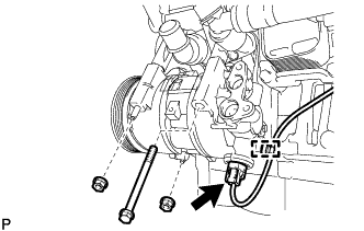
Disconnect the connector and detach the harness clamp.
-
Remove the bolt, 2 nuts and compressor assembly with pulley.
-
Using an E8 "TORX" socket wrench, remove the 2 stud bolts.
-
Remove the compressor pin.
Note
It is not necessary to remove a compressor pin unless it being replaced.
-
-
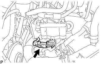
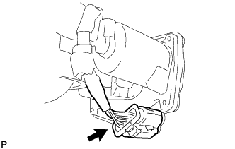
REMOVE GENERATOR ASSEMBLY
-
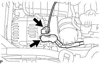
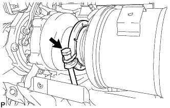
Disconnect the generator connector.
-
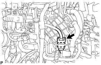
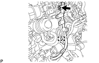
Remove the terminal cap.
-
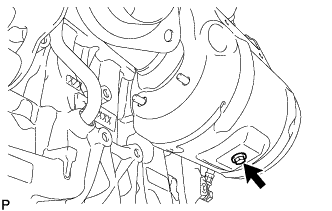
Remove the nut and disconnect the generator wire.
-
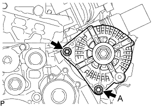
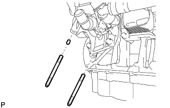
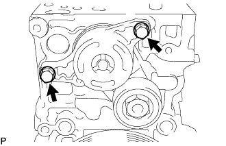
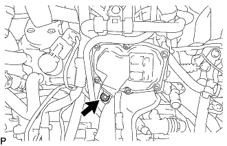
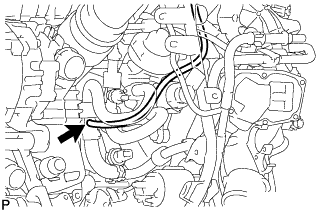
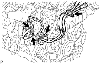
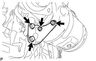
Using an E12 "TORX" socket wrench, remove the 2 bolts as shown in the illustration.
Tech Tips
Bolt A cannot be removed with the generator assembly installed to the vehicle.
-
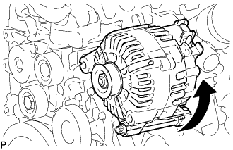
Remove the generator assembly as shown in the illustration.
-
-
REMOVE IDLER PULLEY ASSEMBLY
-
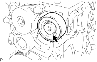
Using a T50 "TORX" socket wrench, loosen the bolt to remove the idler pulley assembly.
Tech Tips
Bolt cannot be removed from the idler pulley assembly.
-
-
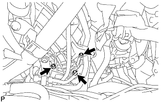
REMOVE ENGINE MOUNTING BRACKET
-
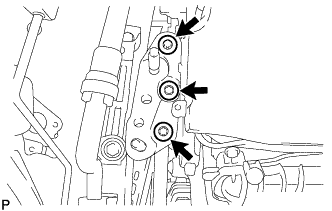
Using an E12 "TORX" socket wrench, remove the 3 bolts and engine mounting bracket.
-
Remove the stud bolt from the engine mounting bracket.
-
-
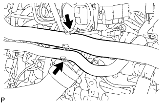
REMOVE V-RIBBED BELT TENSIONER ASSEMBLY
-
Remove the 2 bolts and V-ribbed belt tensioner assembly.
-
-
REMOVE DIESEL THROTTLE BODY ASSEMBLY
-
Detach the water by-pass hose assembly and radiator hose sub-assembly from the air tube assembly.
-
Disconnect the intake air temperature sensor connector.
-
Disconnect the No. 7 engine wire connector and detach the clamp.
-
Using a T27 "TORX" socket wrench, remove the bolt and disconnect the air tube assembly from the cylinder block sub-assembly.
-
Using an E8 "TORX" socket wrench, remove the 3 bolts and diesel throttle body assembly with air tube assembly and gasket.
-
Detach the 2 claws and remove the air tube assembly from the diesel throttle body assembly.
-
Remove the gasket from the air tube assembly.
-
Disconnect the diesel throttle body assembly connector.
-
-
REMOVE ENGINE OIL LEVEL DIPSTICK GUIDE
-
Remove the engine oil level dipstick.
-
Detach the clamp and disconnect the fuel feed pipe sub-assembly from the engine oil level dipstick guide.
-
Using a T25 "TORX" socket wrench, remove the bolt and engine oil level dipstick guide.
-
Remove the O-ring from the engine oil level dipstick guide.
-
-
REMOVE FUEL FEED PIPE SUB-ASSEMBLY
-
Disconnect the nozzle leakage pipe assembly from the fuel feed pipe sub-assembly.
-
Loosen the 2 clamps and disconnect the 2 fuel hoses from the fuel supply pump assembly.
-
Remove the 2 bolts and fuel feed pipe sub-assembly.
-
-
DISCONNECT NO. 2 VACUUM HOSE ASSEMBLY
-
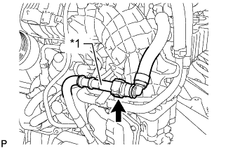
Text in Illustration *1 No. 1 Vacuum Pipe Disconnect the No. 2 vacuum hose assembly from the No. 1 vacuum pipe.
-
Check that there is no damage or foreign matter on the part of the No. 1 vacuum pipe that contacts the No. 2 vacuum hose assembly connector.
-
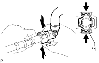
Text in Illustration *1 Retainer 
Pinch 
Pull Out If the No. 2 vacuum hose assembly connector and No. 1 vacuum pipe are stuck together, hold the No. 1 vacuum pipe by hand and push and pull on the No. 2 vacuum hose assembly connector.
Note
-
Check for any dirt and foreign matter contamination in the No. 1 vacuum pipe and around the No. 2 vacuum hose assembly connector. Clean if necessary. Foreign matter may damage the O-ring or cause leaks in the seal between the No. 1 vacuum pipe and No. 2 vacuum hose assembly connector.
-
Do not use any tools to separate the No. 1 vacuum pipe and No. 2 vacuum hose assembly connector.
-
Check for any dirt and foreign matter on the No. 1 vacuum pipe seal surface. Clean if necessary.
-
Protect the disconnected part by covering it with a plastic bag and tape after disconnecting the No. 2 vacuum hose assembly.
-
If the No. 1 vacuum pipe and No. 2 vacuum hose assembly connector are stuck together, pinch the No. 2 vacuum hose assembly connector between your fingers and turn it carefully to free it. Then disconnect the No. 2 vacuum hose assembly.
-
-
Check for dirt or mud on the No. 1 vacuum pipe seal surface of the disconnected No. 1 vacuum pipe. Clean if necessary.
-
To protect the disconnected No. 1 vacuum pipe and No. 2 vacuum hose assembly connector from damage and contamination, cover them with a plastic bag and tape.
-
-
-
REMOVE NO. 2 VACUUM HOSE ASSEMBLY
-
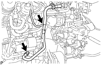
Remove the bolt, nut and No. 2 vacuum hose assembly from the No. 2 engine hanger.
-
-
REMOVE NO. 1 VACUUM PIPE
-
Disconnect the vacuum hose.
-
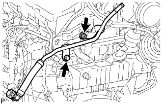
Using an E7 "TORX" socket wrench, remove the bolt and No. 1 vacuum pipe from the cylinder block sub-assembly.
-
Remove the O-ring from the No. 1 vacuum pipe.
-
-
REMOVE INTAKE MANIFOLD
-
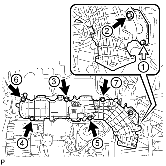
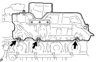
Remove the bolt labeled B and loosen the 6 bolts labeled A in the order shown in the illustration, and then remove the intake manifold.
Text in Illustration Bolt A Bolt B Tech Tips
The bolts labeled A in the illustration cannot be removed from the intake manifold.
-
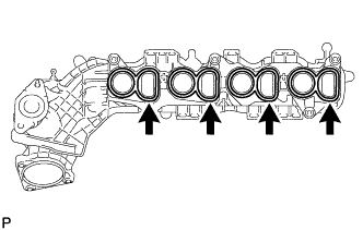
Remove the 4 gaskets from the intake manifold.
-
Remove the gasket from the No. 2 EGR pipe sub-assembly.
-
-
REMOVE NO. 1 MANIFOLD CONVERTER INSULATOR
-
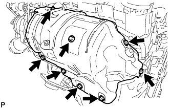
Remove the 7 bolts, nut and No. 1 manifold converter insulator.
-
-
REMOVE EXHAUST MANIFOLD HEAT INSULATOR
-
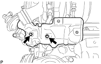
Remove the 2 bolts and No. 1 exhaust manifold heat insulator.
-
-
REMOVE EXHAUST MANIFOLD CONVERTER SUB-ASSEMBLY
-
Remove the 2 bolts, 2 nuts and manifold stay.
-
Remove the bolt and No. 2 manifold converter insulator.
-
Loosen the V-band clamp.
-
Remove the 3 nuts, 2 bolts, V-band clamp, gasket, engine bracket and exhaust manifold converter sub-assembly.
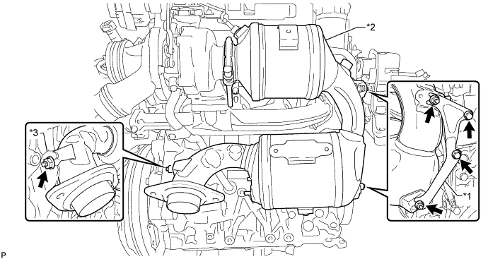
Text in Illustration *1 Engine Bracket *2 Exhaust Manifold Converter Sub-assembly *3 No. 2 Manifold Stay - -
-
-
REMOVE TURBO OIL OUTLET PIPE
-
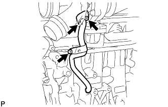
Remove the 3 bolts, turbo oil outlet pipe and gasket.
-
Remove the O-ring from the turbo oil outlet pipe.
-
-
DISCONNECT NO. 1 TURBO OIL PIPE
-
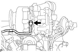
Remove the union bolt and 2 gaskets and disconnect the No. 1 turbo oil pipe.
-
-
REMOVE TURBOCHARGER SUB-ASSEMBLY
-
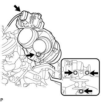
Disconnect the connector from the turbocharger sub-assembly.
-
Remove the 4 bolts, turbocharger sub-assembly and gasket.
-
-
REMOVE EGR COOLER ASSEMBLY WITH EGR VALVE ASSEMBLY
-
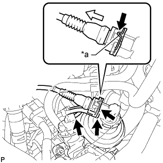
Text in Illustration *a Spring Lock Disconnect the EGR valve assembly connector.
-
Pull the EGR valve assembly connector off of the EGR valve assembly while pushing down the spring lock of the EGR valve assembly connector.
Note
If the EGR valve assembly connector is disconnected without the spring lock being pushed down, the EGR valve assembly connector may be damaged.
-
-
Disconnect the 2 vacuum hoses from the EGR cooler assembly and EGR valve assembly.
-
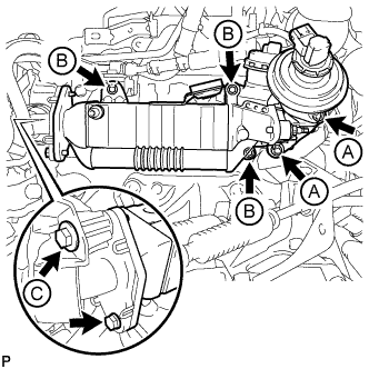
Remove the 7 bolts and EGR cooler assembly with EGR valve assembly.
Tech Tips
-
When removing the bolts labeled A, use a T45 "TORX" socket wrench.
-
When removing the bolts labeled B, use a 6 mm hexagon wrench.
-
The bolt labeled C in the illustration cannot be removed from the intake manifold.
-
-
Remove the 2 gaskets.
-
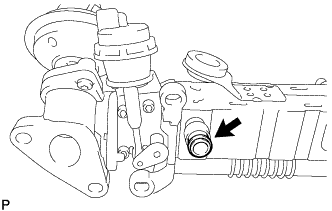
Remove the water pipe from the EGR cooler assembly.
-
-
REMOVE EXHAUST MANIFOLD
-
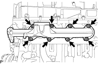
Remove the 8 nuts and exhaust manifold.
-
Remove the 2 gaskets from the cylinder head sub-assembly.
-
-
REMOVE NO. 1 TURBO OIL PIPE
-
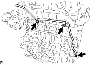
Remove the 2 nuts, union bolt, 2 gaskets and No. 1 turbo oil pipe.
-
-
REMOVE NO. 1 TURBO INSULATOR
-
Remove the 3 bolts and No. 1 turbo insulator.
-
-
REMOVE TURBOCHARGER STAY
-
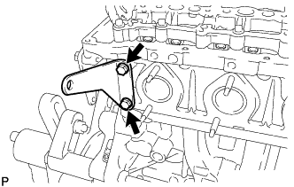
Remove the 2 bolts and turbocharger stay.
-
-
REMOVE EGR VALVE BRACKET
-
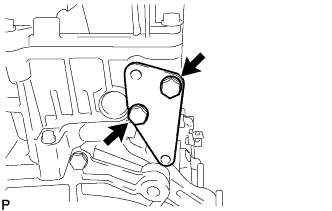
Remove the 2 bolts and EGR valve bracket from the cylinder head sub-assembly.
-
-
REMOVE NO. 2 ENGINE HANGER
-
Remove the 2 bolts and No. 2 engine hanger from the cylinder head sub-assembly.
-
-
REMOVE NO. 1 ENGINE HANGER
-
Remove the bolt and No. 1 engine hanger from the cylinder head sub-assembly..
-
-
REMOVE NO. 3 INJECTION PIPE SUB-ASSEMBLY
-
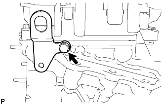
Text in Illustration *1 Rubber Grommet *2 Rubber Mount Using SST, loosen the union nut at the common rail assembly end of the fuel inlet pipe sub-assembly.
SST PZ4TB-04959-10 Note
Reset SST in a timely manner to prevent bending of pressure lines.
-
Using SST, loosen the union nut at the fuel supply pump assembly end of the fuel inlet pipe sub-assembly.
SST PZ4TB-04959-10 Note
Reset SST in a timely manner to prevent bending of pressure lines.
-
Remove the fuel inlet pipe sub-assembly from the rubber grommet and rubber mount.
-
-
REMOVE INJECTION PIPE SUB-ASSEMBLY
Note
Reset SST in a timely manner to prevent bending of pressure lines.
-
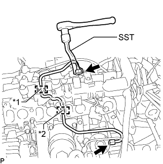
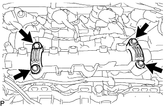
Using SST, loosen the 4 union nuts at the common rail assembly end of the 2 No. 1 injection pipe sub-assemblies and 2 No. 2 injection pipe sub-assemblies.
SST PZ4TB-04959-10 -
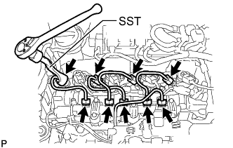
Using SST, loosen the 4 union nuts at the 4 injector assembly ends of the 2 No. 1 injection pipe sub-assemblies and 2 No. 2 injection pipe sub-assemblies.
SST PZ4TB-04959-10 -
Remove the 2 No. 1 injection pipe sub-assemblies and 2 No. 2 injection pipe sub-assemblies.
-
-
REMOVE COMMON RAIL ASSEMBLY
-
Disconnect the fuel pressure sensor connector.
-
Using an E10 "TORX" socket wrench, remove the 4 bolts and 2 common rail assembly brackets.
-
Remove the common rail assembly from the cylinder head cover sub-assembly.
-
-
REMOVE GLOW PLUG ASSEMBLY
-
Disconnect the 4 connectors from the glow plug assemblies.
-
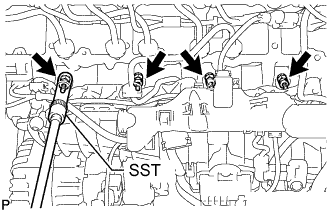
Using SST, remove the 4 glow plug assemblies.
SST PZ4TB-04910-68
-
-
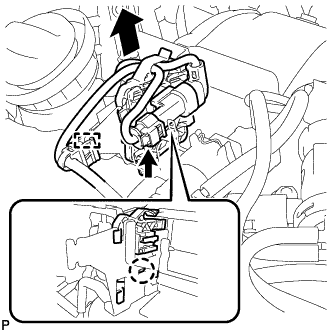
REMOVE VACUUM SWITCHING VALVE ASSEMBLY
-
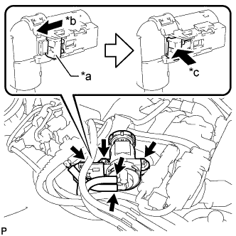
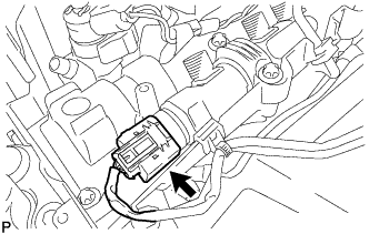
Text in Illustration *a White-colored Lock *b Slide *c Push Slide the white-colored lock of the vacuum switching valve assembly connector as shown in the illustration to release it and disconnect the vacuum switching valve assembly connector.
-
Disconnect the 2 vacuum hoses.
-
Remove the 2 nuts and vacuum switching valve assembly.
-
-
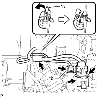
REMOVE EGR BYPASS VALVE SWITCHING VALVE ASSEMBLY
-
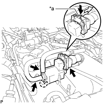
Text in Illustration *a Spring Lock Disconnect the EGR bypass valve switching valve assembly connector.
-
Pull the EGR bypass valve switching valve assembly connector off of the EGR bypass valve switching valve assembly while pushing down the spring lock of the EGR bypass valve switching valve assembly connector.
Note
If the EGR bypass valve switching valve assembly connector is disconnected without the spring lock being pushed down, the EGR bypass valve switching valve assembly connector may be damaged.
-
-
Disconnect the 2 vacuum hoses.
-
Detach the claw and remove the EGR bypass valve switching valve assembly.
-
-
REMOVE VACUUM CONTROL VALVE BRACKET
-
Disconnect the differential pressure sensor connector.
-
Detach the wire harness clamp.
-
Remove the claw as shown in the illustration, and then slide the bracket clamp with differential pressure sensor to disconnect the bracket clamp with differential pressure sensor from the vacuum control valve bracket.
-
Text in Illustration *a Air Fuel Ratio Sensor Connector *b Exhaust Gas Temperature Sensor Connector *c Clamp Disconnect the exhaust gas temperature sensor connector.
-
Disconnect the air fuel ratio sensor connector.
-
Raise the air fuel ratio sensor connector from the vacuum control valve bracket.
-
Move the clamp as shown in the illustration, and disconnect the air fuel ratio sensor and exhaust gas temperature sensor.
Note
Disconnect the sensors while opening the clamp.
-
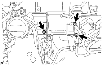
Using a T45 "TORX" socket wrench, remove the 3 screws and disconnect the vacuum control valve bracket.
-
-
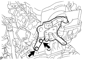
REMOVE DRIVE SHAFT BEARING BRACKET
-
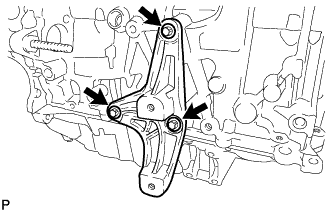
Remove the 3 bolts and drive shaft bearing bracket.
-