ENGINE ASSEMBLY INSTALLATION

CAUTION:
As the engine assembly with transaxle assembly is extremely heavy, the engine lifter may suddenly drop if the instructions listed in the repair manual are not followed. Therefore, always follow the instructions listed in the repair manual when performing this procedure.
-
INSTALL ENGINE MOUNTING INSULATOR LH
Tech Tips
Perform this procedure only when replacement of the engine mounting insulator LH is necessary.
-
Install the engine mounting insulator LH with the 4 bolts.
- Torque:
- 95 N*m { 969 kgf*cm, 70 ft.*lbf }
-
-
INSTALL ENGINE MOUNTING BRACKET LH
Tech Tips
Perform this procedure only when replacement of the engine mounting bracket LH is necessary.
-
Apply adhesive to 2 to 3 threads at the end of each bolts.
Adhesive Toyota Genuine Adhesive 1324, Three Bond 1324 or equivalent -
Install the engine mounting bracket LH with the 4 bolts.
- Torque:
- 64 N*m { 653 kgf*cm, 47 ft.*lbf }
-
-
INSTALL REAR ENGINE MOUNTING INSULATOR
-
Install the rear engine mounting insulator with the 2 bolts and 2 nuts.
- Torque:
- 95 N*m { 969 kgf*cm, 70 ft.*lbf }
-
-
INSTALL FRONT ENGINE MOUNTING INSULATOR
-
Install the front engine mounting insulator to the front crossmember sub-assembly with the 2 bolts.
- Torque:
- 95 N*m { 969 kgf*cm, 70 ft.*lbf }
-
-
REMOVE ENGINE FROM ENGINE STAND
Note
-
Pay attention to the angle of the sling device as the engine assembly or engine hangers may be damaged or deformed if the angle is incorrect.
-
With the exception of installing the engine assembly to an engine stand or removing the engine assembly from an engine stand, do not perform any work on the engine assembly while it is suspended, as doing so is dangerous.
-
Install a sling device and chain block to the engine assembly and hang the engine assembly.
-
Remove the engine assembly from the engine stand.
-
-
INSTALL MANUAL TRANSAXLE ASSEMBLY
-
INSTALL REAR ENGINE MOUNTING BRACKET
-
Install the rear engine mounting bracket with the 5 bolts.
- Torque:
- 45 N*m { 459 kgf*cm, 33 ft.*lbf }
-
-
INSTALL FRONT ENGINE MOUNTING BRACKET
-
Install the front engine mounting bracket with the 4 bolts.
- Torque:
- 64 N*m { 653 kgf*cm, 47 ft.*lbf }
-
-
INSTALL STARTER ASSEMBLY
-
Using an E14 "TORX" socket wrench, install the starter assembly with the 2 bolts.
- Torque:
- 64 N*m { 653 kgf*cm, 47 ft.*lbf }
-
Connect the engine wire with the nut to the starter assembly.
- Torque:
- 5.0 N*m { 51 kgf*cm, 44 in.*lbf }
-
Connect the No. 2 engine wire with the nut and close the terminal cap.
- Torque:
- 9.8 N*m { 100 kgf*cm, 87 in.*lbf }
-
-
INSTALL NO. 1 AIR TUBE ASSEMBLY
-
Install the No. 1 air tube assembly to the manual transaxle assembly with the 2 bolts.
- Torque:
- 20 N*m { 204 kgf*cm, 15 ft.*lbf }
-
Connect the No. 4 water by-pass hose to the EGR cooler assembly.
-
Connect the compressor outlet elbow to the turbocharger sub-assembly.
-
-
INSTALL ENGINE WIRE
-
Connect the connectors, attach the clamps and install the engine wire to the engine assembly with the bracket bolts.
-
-
INSTALL REAR ENGINE MOUNTING INSULATOR
-
Install the rear engine mounting insulator with the bolt.
- Torque:
- 95 N*m { 969 kgf*cm, 70 ft.*lbf }
-
-
INSTALL ENGINE WITH TRANSAXLE
-
Place the engine assembly on an engine lifter, and then remove the sling device and chain block from the engine assembly.
Note
-
Place wooden blocks or plate lift attachments so that the engine assembly is level.
-
With the exception of installing the engine assembly to an engine stand or removing the engine assembly from an engine stand, do not perform any work on the engine while it is suspended, as doing so is dangerous.
-
Never install attachments to the oil pan sub-assembly of the engine assembly or transaxle assembly as doing so may deform the oil pan sub-assembly.
-
-
Using the engine lifter, slowly raise the engine assembly and install it to the vehicle, and then install the intermediate shaft to the pinion.
CAUTION:
Do not raise the engine assembly more than necessary. If the engine assembly is raised excessively, the vehicle may also be lifted up.
Note
-
Make sure that the engine assembly is clear of all wiring and hoses.
-
While raising the engine assembly into the vehicle, do not allow it to contact the vehicle.
-
Align the matchmarks on the intermediate shaft and pinion.
-
-
Temporarily install the front suspension crossmember sub-assembly with the 2 bolts.
-
Temporarily install the front suspension rear brace RH and front suspension rear brace LH with the 6 bolts.
-
Connect the front engine mounting insulator with the through bolt and nut.
- Torque:
- 145 N*m { 1479 kgf*cm, 107 ft.*lbf }
-
Connect the engine mounting insulator LH with the bolt and nut.
- Torque:
- 56 N*m { 571 kgf*cm, 41 ft.*lbf }
Tech Tips
While holding the bolt in place, tighten the nut.
-
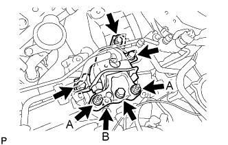
Install the engine mounting insulator RH with the 4 bolts and 3 nuts.
- Torque:
- for bolt and nut A
- 95 N*m { 969 kgf*cm, 70 ft.*lbf }
- for nut B
- 52 N*m { 530 kgf*cm, 38 ft.*lbf }
-
Attach the clamp and connect the air conditioner tube and accessory assembly.
-
Attach the 2 clamps and connect the suction pipe sub-assembly.
-
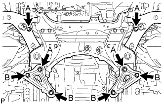
Tighten the 8 front suspension crossmember sub-assembly and front suspension member rear brace bolts.
- Torque:
- for bolt A
- 137 N*m { 1397 kgf*cm, 101 ft.*lbf }
- for bolt B
- 93 N*m { 948 kgf*cm, 69 ft.*lbf }
-
Install the front crossmember sub-assembly with the 4 bolts.
- Torque:
- 99 N*m { 1010 kgf*cm, 73 ft.*lbf }
-
Connect the cable bracket with the bolt.
- Torque:
- 5.0 N*m { 51 kgf*cm, 44 in.*lbf }
-
-
INSTALL FRONT SUSPENSION MEMBER REINFORCEMENT RH
-
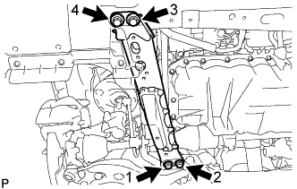
Install the front suspension member reinforcement RH with the 4 bolts.
- Torque:
- 99 N*m { 1010 kgf*cm, 73 ft.*lbf }
Note
Tighten the bolts in the order shown in the illustration.
-
-
INSTALL FRONT SUSPENSION MEMBER REINFORCEMENT LH
-
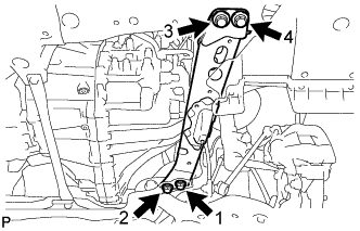
Install the front suspension member reinforcement LH with the 4 bolts.
- Torque:
- 99 N*m { 1010 kgf*cm, 73 ft.*lbf }
Note
Tighten the bolts in the order shown in the illustration.
-
-
INSTALL FRONT LOWER ENGINE MOUNTING BRACKET REINFORCEMENT
-
Install the front lower engine mounting bracket reinforcement with the 2 bolts.
- Torque:
- 99 N*m { 1010 kgf*cm, 73 ft.*lbf }
-
-
INSTALL FRONT DRIVE SHAFT HOLE SNAP RING LH
-
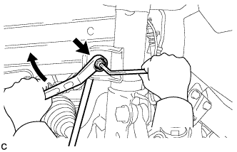
Install a new front drive shaft hole snap ring LH.
Note
Be careful not to damage the spline of the front drive inboard joint LH.
-
-
INSTALL FRONT DRIVE SHAFT ASSEMBLY LH
-
Coat the spline of the front drive inboard joint LH with "Toyota Genuine Manual Transmission Gear Oil LV" or "API GL-4 and SAE 75W".
-
Apply a light coat of MP grease to the front drive shaft hole snap ring LH of the front drive inboard joint LH.
-
Coat the lip of the transaxle case oil seal LH with MP grease.
-
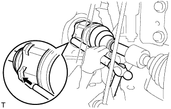
Align the shaft splines and tap in the front drive shaft assembly LH with a brass bar and hammer.
Note
-
Make sure that the front drive shaft hole snap ring LH opening is facing downwards when installing the front drive shaft assembly LH.
-
Be careful not to damage the transaxle case oil seal LH, front axle inboard joint boot and front drive shaft dust cover LH.
-
-
-
INSTALL FRONT DRIVE SHAFT ASSEMBLY RH
-
Coat the spline of the front drive inboard joint RH with "Toyota Genuine Manual Transmission Gear Oil LV" or "API GL-4 and SAE 75W".
-
Coat the lip of the transaxle case oil seal RH with MP grease.
-
Align the shaft splines and securely insert the front drive shaft assembly RH.
-
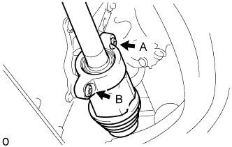
Using a T50 ''TORX'' socket wrench, after temporarily installing bolt A, tighten the 2 bolts in the order A, B.
- Torque:
- 64 N*m { 650 kgf*cm, 47 ft.*lbf }
Note
Be careful not to damage the transaxle case oil seal RH, front axle inboard joint boot and front drive shaft dust cover RH.
-
-
INSTALL FRONT AXLE ASSEMBLY LH
-
INSTALL FRONT AXLE ASSEMBLY RH
Tech Tips
Perform the same procedure as for the LH side.
-
CONNECT FRONT STABILIZER LINK ASSEMBLY LH
-
Connect the front stabilizer link assembly to the front shock absorber with coil spring with the nut.
- Torque:
- 74 N*m { 755 kgf*cm, 55 ft.*lbf }
Tech Tips
If the ball joint turns together with the nut, use a 6 mm hexagon wrench to hold the stud bolt.
-
-
CONNECT FRONT STABILIZER LINK ASSEMBLY RH
Tech Tips
Perform the same procedure as for the LH side.
-
INSTALL FRONT AXLE SHAFT NUT LH
-
Clean the threaded parts on the drive shaft and a new axle shaft nut using a non-residue solvent.
Note
-
Be sure to perform this work for a new drive shaft.
-
Keep the threaded parts free of oil and foreign objects.
-
-
Using a 30 mm socket wrench, temporarily install the axle shaft nut.
- Torque:
- for Gasoline Engine
- 216 N*m { 2203 kgf*cm, 159 ft.*lbf }
- for Diesel Engine
- 292 N*m { 2978 kgf*cm, 215 ft.*lbf }
Tech Tips
Stake the nut after inspecting for looseness and runout in the following steps.
-
-
INSTALL FRONT AXLE SHAFT NUT RH
Tech Tips
Perform the same procedure as for the LH side.
-
STAKE FRONT AXLE SHAFT NUT LH
-
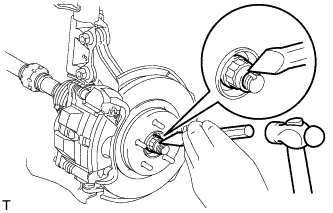
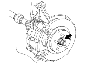
Using a chisel and a hammer, stake the front axle shaft nut.
-
-
STAKE FRONT AXLE SHAFT NUT RH
Tech Tips
Perform the same procedure as for the LH side.
-
INSTALL NO. 1 STEERING COLUMN HOLE COVER SUB-ASSEMBLY
-
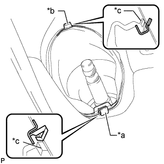
Text in Illustration *a Clip A *b Clip B *c Lip Attach clip B to the body and install the No. 1 steering column hole cover to the body with clip A.
Note
Make sure that the lip of the No. 1 steering column hole cover is not damaged.
-
-
CONNECT NO. 2 STEERING INTERMEDIATE SHAFT ASSEMBLY
-
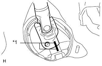
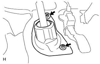
Text in Illustration *1 Matchmark Align the matchmarks on the No. 2 steering intermediate shaft assembly and steering intermediate shaft assembly.
-
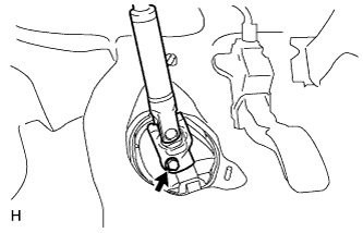
Install the bolt.
- Torque:
- 35 N*m { 360 kgf*cm, 26 ft.*lbf }
-
-
INSTALL COLUMN HOLE COVER SILENCER SHEET
-
Install the column hole cover silencer sheet with the 2 clips.
-
Install the floor carpet.
-
-
CONNECT CLUTCH RELEASE CYLINDER ASSEMBLY
-
Connect the clutch release cylinder assembly and clutch flexible hose bracket with the 4 bolts.
- Torque:
- 12 N*m { 122 kgf*cm, 9 ft.*lbf }
-
-
CONNECT TRANSMISSION CONTROL CABLE ASSEMBLY
-
Connect the 2 transmission control cable assemblies to the transmission control cable bracket with 2 new clips.
-
Connect the 2 transmission control cable assemblies to the manual transaxle assembly with the 2 pins.
-
-
INSTALL AIR CLEANER BRACKET
-
Install the air cleaner bracket with the 3 bolts.
- Torque:
- 7.0 N*m { 71 kgf*cm, 62 in.*lbf }
-
-
INSTALL FUEL FILTER SUPPORT
-
Install the fuel filter support with the 3 bolts.
- Torque:
- 18 N*m { 178 kgf*cm, 13 ft.*lbf }
-
Attach the clamp to connect the wire harness.
-
Attach the 2 clamps and connect the engine wire.
-
Connect the connector.
-
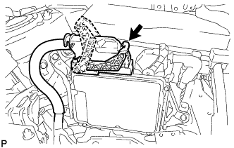
Connect the ECM connector and lower the lever.
Note
-
When connecting the ECM connector, make sure that dirt, water and other foreign matter is not stuck between the ECM connector and ECM.
-
Make sure that the lever is securely lowered.
-
-
-
INSTALL FUEL FILTER ASSEMBLY
-
Install the fuel filter cover to a new fuel filter assembly with the bolt.
- Torque:
- 7.0 N*m { 71 kgf*cm, 62 in.*lbf }
-
Install the fuel filter assembly to the fuel filter support with the nut.
- Torque:
- 18 N*m { 178 kgf*cm, 13 ft.*lbf }
-
Connect the connector to the fuel filter assembly.
-
Connect the No. 1 fuel hose and No. 3 fuel hose to the fuel filter assembly Click here.
-
Install the No. 2 fuel pipe clamp to the No. 1 fuel hose.
-
Install the No. 1 fuel filter protector with the 2 nuts.
- Torque:
- 18 N*m { 178 kgf*cm, 13 ft.*lbf }
-
-
CONNECT HOSES AND CONNECTORS
-
Connect the ground cable with the bolt.
- Torque:
- 13 N*m { 127 kgf*cm, 9 ft.*lbf }
-
Connect the 2 connectors, attach the 2 claws to install the No. 1 engine room relay block and install the 2 nuts.
- Torque:
- 8.4 N*m { 86 kgf*cm, 74 in.*lbf }
-
Install the No. 1 engine room relay block cover.
-
-
CONNECT INLET HEATER WATER HOSE
-
Connect the inlet heater water hose to the No. 1 air tube assembly, and slide the clamp to secure the hose.
-
-
CONNECT WATER HOSE SUB-ASSEMBLY
-
Connect the water hose to the No. 1 air tube assembly, and slide the clamp to secure the hose.
-
-
CONNECT NO. 2 FUEL HOSE
-
Connect the No. 2 fuel hose to the fuel feed pipe sub-assembly, and slide the clamp to secure the hose.
-
-
CONNECT FUEL HOSE
-
Connect the fuel hose to the fuel feed pipe sub-assembly, and slide the clamp to secure the hose.
-
-
CONNECT VACUUM HOSE
-
Connect the vacuum hose to the No. 2 vacuum hose assembly, and slide the clamp to secure the hose.
-
-
INSTALL RADIATOR HOSE SUB-ASSEMBLY
-
Install the radiator hose sub-assembly to the outlet.
-
Connect the radiator hose sub-assembly, and slide the clamp to secure the hose.
-
-
INSTALL WATER BY-PASS HOSE ASSEMBLY
-
Connect the water by-pass hose assembly to the water by-pass pipe.
-
Connect the water by-pass hose assembly to the No. 1 air tube assembly, and slide the clamp to secure the hose.
-
-
INSTALL RADIATOR RESERVOIR ASSEMBLY
-
Install the radiator reservoir assembly with the 2 bolts.
- Torque:
- 5.0 N*m { 51 kgf*cm, 44 in.*lbf }
-
Connect the No. 2 water by-pass hose assembly to the radiator reservoir assembly, and slide the clamp to secure the hose.
-
Connect the water by-pass hose assembly to the radiator reservoir assembly, and slide the clamp to secure the hose.
-
-
INSTALL AIR CLEANER CASE SUB-ASSEMBLY
-
Install the air cleaner case sub-assembly with the 3 bolts.
- Torque:
- 7.0 N*m { 71 kgf*cm, 62 in.*lbf }
-
-
INSTALL AIR CLEANER FILTER ELEMENT SUB-ASSEMBLY
-
INSTALL AIR CLEANER CAP SUB-ASSEMBLY WITH AIR CLEANER HOSE ASSEMBLY
-
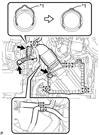
Text in Illustration *1 Retainer Connect the air cleaner hose assembly to the turbocharger sub-assembly and lock the retainer as shown in the illustration.
-
Attach the 2 clamps to install the air cleaner cap sub-assembly.
-
Connect the ventilation hose to the cylinder head cover sub-assembly.
-
Attach the clamp and connect the No. 2 fuel hose to the air cleaner hose assembly.
-
Attach the clamp and connect the No. 1 fuel hose to the air cleaner hose assembly.
-
Attach the clamp and connect the vacuum hose to the air cleaner hose assembly.
-
Attach the clamp and connect the mass air flow meter sub-assembly connector.
-
-
CONNECT DISCHARGE HOSE SUB-ASSEMBLY (w/ Air Conditioning System)
-
Remove the attached vinyl tape from the hose and compressor.
-
Apply sufficient compressor oil to a new O-ring and the fitting surface of the compressor assembly with pulley.
Compressor oil ND-OIL 8 or equivalent -
Install the O-ring to the discharge hose sub-assembly.
-
Connect the discharge hose sub-assembly to the compressor assembly with pulley with the bolt.
- Torque:
- 9.8 N*m { 100 kgf*cm, 87 in.*lbf }
-
-
CONNECT SUCTION HOSE SUB-ASSEMBLY (w/ Air Conditioning System)
-
Remove the attached vinyl tape from the hose and compressor.
-
Apply sufficient compressor oil to a new O-ring and the fitting surface of the compressor assembly with pulley.
Compressor oil ND-OIL 8 or equivalent -
Install the O-ring to the suction hose sub-assembly.
-
Connect the suction hose sub-assembly to the compressor assembly with pulley with the bolt.
- Torque:
- 9.8 N*m { 100 kgf*cm, 87 in.*lbf }
-
-
INSTALL RADIATOR ASSEMBLY
-
INSTALL BATTERY CARRIER
-
Install the battery carrier with the 4 bolts.
- Torque:
- 19 N*m { 189 kgf*cm, 14 ft.*lbf }
-
Attach the 2 clamps to connect the engine wire.
-
-
INSTALL BATTERY TRAY
-
INSTALL BATTERY
-
INSTALL BATTERY INSULATOR
-
INSTALL BATTERY CLAMP SUB-ASSEMBLY
-
Attach the hook of the battery clamp sub-assembly to the battery carrier.
-
Partially tighten the nut and temporarily install the bolt.
-
Adjust the battery clamp sub-assembly position.
-
Tighten the nut and bolt.
- Torque:
- for bolt
- 17 N*m { 168 kgf*cm, 12 ft.*lbf }
- for nut
- 3.5 N*m { 36 kgf*cm, 31 in.*lbf }
-
-
INSTALL FRONT EXHAUST PIPE ASSEMBLY
-
ADD MANUAL TRANSAXLE OIL
-
Add manual transaxle oil.
Manual Transaxle Oil "Toyota Genuine Manual Transmission Gear Oil LV" or "API GL-4 and SAE 75W" Capacity (Reference) 2.1 liters (2.2 US qts, 1.8 Imp. qts) -
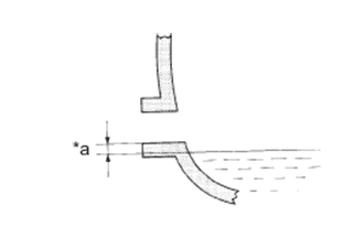
Text in Illustration *a 0 to 5 mm (0 to 0.196 in.) Check that the oil surface is within 5 mm (0.196 in.) of the bottom of the manual transmission filler plug opening.
-
Install a new gasket and the transmission filler plug.
- Torque:
- 39 N*m { 400 kgf*cm, 29 ft.*lbf }
Note
-
When adding transaxle oil, make sure the vehicle is level.
-
An excessively large or small amount of oil may cause problems.
-
After adding oil, drive the vehicle and recheck the oil level.
-
-
ADD ENGINE OIL
-
Add new engine oil.
Standard engine oil Toyota recommends the use of approved "Toyota Genuine Motor Oil 5W-30 Premium Fuel Economy for 1WW/2WW engines" or equivalent. Standard capacity (Drain and refill with oil filter change) 5.2 liters (5.5 US qts, 4.6 Imp. qts) Tech Tips
Refer to "OIL SPEC LIST" for the standard engine oil.
-
-
ADD ENGINE COOLANT
CAUTION:
Do not remove the reservoir cap and air release valve while the engine and radiator assembly are still hot. Pressurized, hot engine coolant and steam may be released and cause serious burns.
-
Tighten the radiator drain cock plug by hand.
-
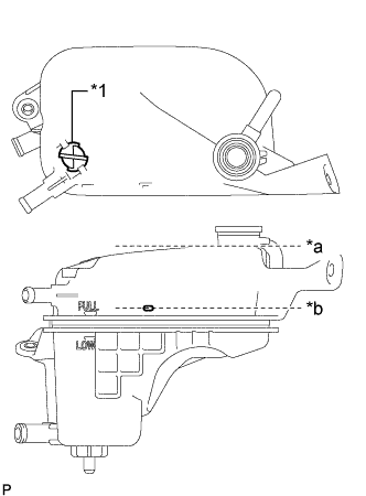
Text in Illustration *1 Air Release Valve *a Radiator Reservoir Assembly Filler Neck *b Pour Limit Line Remove the air release valve.
-
Add engine coolant to the pour limit line of the radiator reservoir assembly.
Standard Capacity Item Specified Condition w/o Combustion Type Power Heater 7.0 liters (7.4 US qts, 6.2 Imp. qts) w/ Combustion Type Power Heater 7.3 liters (7.7 US qts, 6.4 Imp. qts) Note
Never use water as a substitute for engine coolant.
Tech Tips
Toyota recommends the use of approved "Toyota Premium Long Life Coolant for 1WW/2WW engines" or equivalent.
-
Press the No. 2 radiator hose and radiator hose sub-assembly several times by hand, and then check the level of the engine coolant.
If the coolant level is low, add engine coolant.
-
Install the air release valve.
-
Add engine coolant to the filler neck of the radiator reservoir assembly.
-
Install the reservoir cap.
-
Start the engine, and warm it up until the cooling fan operates.
Note
-
Before starting the engine, turn the A/C switch off.
-
Adjust the air conditioning temperature setting to MAX (HOT).
-
Adjust the air conditioning blower setting to Lo.
-
-
Maintain the engine speed at 2000 to 2500 rpm and warm up the engine until the cooling fan operates.
Note
-
Make sure that the radiator reservoir assembly still has some engine coolant in it.
-
Pay attention to the needle of the water temperature meter. Make sure that the needle does not show an abnormally high temperature.
-
If there is not enough engine coolant, the engine may burn out or overheat.
-
Immediately after starting the engine, if the radiator reservoir assembly does not have any coolant, perform the following: 1) stop the engine, 2) wait until the engine coolant has cooled down, and 3) add engine coolant until the coolant is filled to the pour limit line.
-
Until the coolant level has stabilized, run the engine at 2000 rpm.
-
-
Press the No. 2 radiator hose and radiator hose sub-assembly several times by hand to bleed air.
CAUTION:
-
Wear protective gloves.
-
Be careful as the radiator hoses are hot.
-
Keep your hands away from the cooling fan.
-
-
Stop the engine and wait until the coolant cools down to ambient temperature.
-
Check that the coolant level is between the FULL and LOW line.
If the coolant level is below the LOW line, repeat all of the procedures above.
If the coolant level is above the FULL line, drain coolant so that the coolant level is between the FULL and LOW line.
-
-
INSTALL FRONT BUMPER COVER
-
INSTALL OUTER COWL TOP PANEL
-
Install the outer cowl top panel with the 9 bolts.
- Torque:
- 12 N*m { 122 kgf*cm, 9 ft.*lbf }
-
-
INSTALL FRONT WIPER MOTOR AND LINK ASSEMBLY
-
CONNECT CABLE TO POSITIVE BATTERY TERMINAL
-
CONNECT CABLE TO NEGATIVE BATTERY TERMINAL
Note
When disconnecting the cable, some systems need to be initialized after the cable is reconnected Click here.
-
CHARGE REFRIGERANT (w/ Air Conditioning System)
- SST
- 09985-20010 ( 09985-02130, 09985-02150, 09985-02090, 09985-02110, 09985-02010, 09985-02050, 09985-02060, 09985-02070 )
-
Perform vacuum purging using a vacuum pump.
-
Charge refrigerant HFC-134a (R134a).
Standard 440 +/-30 g (15.5 +/-1.1 oz) 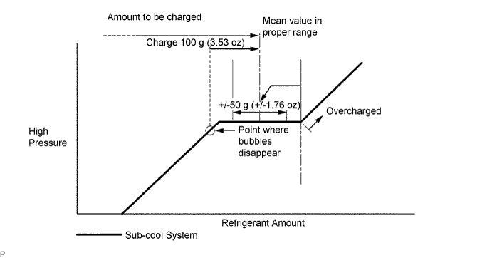
Note
-
Do not operate the cooler compressor before charging refrigerant as the cooler compressor will not work properly without any refrigerant, and will overheat.
-
Approximately 100 g (3.53 oz) of refrigerant may need to be charged after bubbles disappear. The refrigerant amount should be checked by measuring its quantity, and not with the sight glass.
-
-
PERFORM REGISTRATION
-
WARM UP ENGINE (w/ Air Conditioning System)
-
Warm up the engine at less than 1850 rpm for 2 minutes or more after charging the refrigerant.
Note
Be sure to warm up the compressor by turning the A/C switch on after removing and installing the cooler refrigerant lines (including the compressor) to prevent damage to the compressor.
-
-
INSPECT FOR REFRIGERANT LEAK (w/ Air Conditioning System)
-
After recharging the refrigerant gas, check for refrigerant gas leakage using a halogen leak detector.
-
Perform the operation observing the following instructions:
-
Stop the engine.
-
Secure good ventilation (the halogen leak detector may react to volatile gases other than refrigerant, such as evaporated gasoline or exhaust gas).
-
Repeat the test 2 or 3 times.
-
Make sure that some refrigerant remains in the refrigeration system.
Tech Tips
When the compressor is off: approximately 392 to 588 kPa (4.0 to 6.0 kgf/cm2, 57 to 85 psi).
-
-
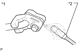
Text in Illustration *1 Check for Leakage *2 Halogen Leak Detector Using a halogen leak detector, check the refrigerant line for leakage.
-
If a gas leak is not detected from the drain hose, remove the blower motor control (blower resistor) from the cooling unit. Insert the halogen leak detector sensor into the unit and check for gas leakage.
-
Disconnect the pressure switch connector and wait for approximately 20 minutes. Bring the halogen leak detector close to the pressure switch and check for gas leakage.
-
-
INSPECT FOR OIL LEAK
-
Start the engine. Make sure that there are no oil leaks from the areas that were worked on.
-
-
INSPECT FOR COOLANT LEAK
-
Remove the reservoir cap.
CAUTION:
To avoid the danger of being burned, do not remove the reservoir cap while the engine and radiator assembly are still hot. Thermal expansion will cause hot engine coolant and steam to blow out from the radiator assembly.
-
Fill the radiator assembly with coolant, and then attach a radiator cap tester.
-
Warm up the engine.
-
Pump the radiator cap tester to 143 kPa (1.5 kgf/cm2, 20.7 psi), and then check that the pressure does not drop.
If the pressure drops, check the hoses, radiator assembly and engine water pump assembly for leakage.
If there are no signs of external coolant leaks, check the heater core, cylinder block and head.
-
Reinstall the reservoir cap.
-
-
INSPECT FOR FUEL LEAK
-
Check fuel pump operation.
-
Connect the GTS to the DLC3.
-
Turn the ignition switch to ON and turn the GTS on.
Note
Do not start the engine.
-
Enter the following menus: Powertrain / Engine and ECT / Active Test / Actuator Test of FPC (EU5).
-
Check for pressure in the fuel inlet tube from the fuel line. Check that sounds of fuel flowing from the fuel tank can be heard. If no sounds can be heard, check the No. 1 integration relay, fuel suction with pump and gauge tube assembly, ECM and wiring connectors.
-
-
Inspect for fuel leaks.
-
Check that there are no fuel leaks from the fuel system after doing any maintenance or repairs. If there is a fuel leak, repair or replace parts as necessary.
-
-
Turn the ignition switch off.
-
Disconnect the GTS from the DLC3.
-
-
INSPECT FOR EXHAUST GAS LEAK
If gas is leaking, tighten the areas necessary to stop the leak. Replace damaged parts as necessary.
-
INSTALL REAR ENGINE UNDER COVER RH
-
Install the rear engine under cover RH with the 5 clips.
-
-
INSTALL REAR ENGINE UNDER COVER LH
-
Install the rear engine under cover LH with the 5 clips.
-
-
INSTALL NO. 2 ENGINE UNDER COVER
-
Install the No. 2 engine under cover with the 4 clips.
-
-
INSTALL NO. 1 ENGINE UNDER COVER
-
Install the No. 1 engine under cover with the 11 clips and 6 bolts.
-
-
INSTALL FRONT LOWER BUMPER ABSORBER
-
Insert the 2 hooks of the front lower bumper absorber into the installation holes in the body to install the front lower bumper absorber.
-
Install the 4 bolts.
-
Install the 2 clips.
-
-
INSTALL NO. 1 ENGINE COVER
-
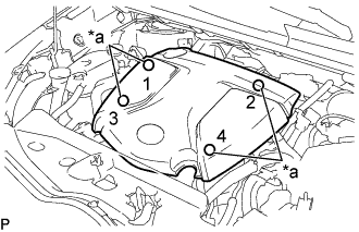
Text in Illustration *a Installation Points Attach the 4 clips to install the No. 1 engine cover.
Tech Tips
When attaching the clips, press the protrusions on the top of the No. 1 engine cover at the clip installation points.
-
-
CHECK IDLE SPEED
Note
-
Turn all the electrical systems and A/C off.
-
Inspect the engine idle speed with the cooling fan off.
-
When checking the idle speed, move the shift lever to neutral.
Tech Tips
-
For more information about the GTS, refer to its operator's manual.
-
If the GTS is not available, use a tachometer as a substitute.
-
Warm up and stop the engine.
-
When using the GTS:
-
Connect the GTS to the DLC3.
-
Start the engine and idle it.
-
Enter the following menus: Powertrain / Engine and ECT / Data List / Engine Speed.
-
-
When not using the GTS:
-
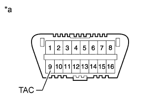
Text in Illustration *a Front view of DLC3 Connect a tachometer tester probe of a tachometer to terminal 9 (TAC) of the DLC3 with SST.
- SST
- 09843-18040
-
Start the engine and idle it.
-
-
Inspect the engine idle speed.
Standard idle speed (Reference) 830 rpm -
Turn the ignition switch off.
-
Disconnect the GTS or tachometer tester probe from the DLC3.
-
-
CHECK MAXIMUM ENGINE SPEED
-
Start the engine.
-
Fully depress the accelerator pedal.
-
Check the maximum engine speed.
Maximum engine speed (Reference) 3800 rpm
-
-
INSTALL RADIATOR SUPPORT OPENING COVER
-
Attach the 4 hooks and install the radiator support opening cover.
-
Install the 3 clips.
-
-
ADJUST FRONT WHEEL ALIGNMENT
-
CHECK ABS SPEED SENSOR SIGNAL
-
Check the speed sensor signal Click here.
-