-
After the engine has stopped, wait at least 1 minute before releasing the high pressure lines.
-
When working on the fuel circuit, protect the generator assembly against dirt contamination.
Cover the generator assembly with suitable materials.
Failure to comply with this procedure may result in a generator assembly malfunction.
-
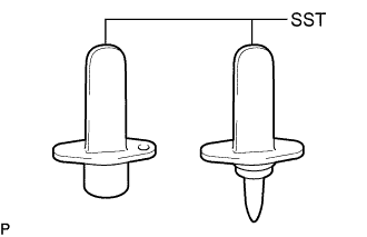
After disconnecting the pressure line, it is absolutely essential to seal the injector assemblies and the common rail assembly with SST.
SST PZ4TB-04941-79
- Click here
PRECAUTION
Note:After turning the ignition switch off, waiting time may be required before disconnecting the cable from the battery terminal. Therefore, make sure to read the disconnecting the cable from the battery terminal notice before proceeding with work (Click here).
- Click here
DISCONNECT CABLE FROM NEGATIVE BATTERY TERMINAL
Note:When disconnecting the cable, some systems need to be initialized after the cable is reconnected (Click here).
- Click here
REMOVE CAMSHAFT AND NO. 2 CAMSHAFT
- Click here
REMOVE EXHAUST MANIFOLD
- Click here
REMOVE EGR VALVE BRACKET
-
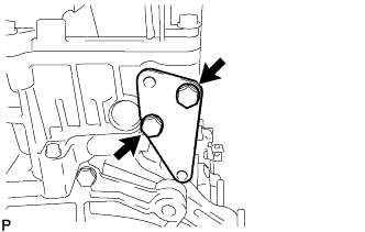
Remove the 2 bolts and EGR valve bracket from the cylinder head sub-assembly.
-
- Click here
REMOVE NO. 1 TURBO INSULATOR
-
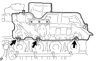
Remove the 3 bolts and No. 1 turbo insulator.
-
- Click here
DISCONNECT RADIATOR RESERVOIR ASSEMBLY
-
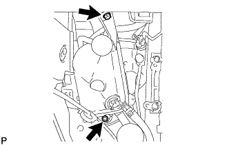
Remove the 2 bolts and disconnect the radiator reservoir assembly.
-
- Click here
REMOVE ENGINE MOUNTING INSULATOR SUB-ASSEMBLY RH
-
Detach the clamp to disconnect the air conditioner tube and accessory assembly.
-
Detach the 2 clamps to disconnect the suction pipe sub-assembly.
-
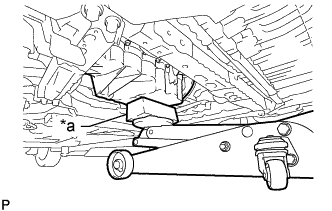
Place a wooden block between a jack and the oil pan sub-assembly.
Table 1. Text in Illustration *a Wooden Block -
Support the engine slightly.
-
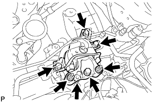
Remove the 4 bolts, 3 nuts and engine mounting insulator sub-assembly RH.
Tip:Supporting the engine slightly makes the engine mounting insulator sub-assembly RH easier to remove.
-
- Click here
REMOVE GLOW PLUG ASSEMBLY
-
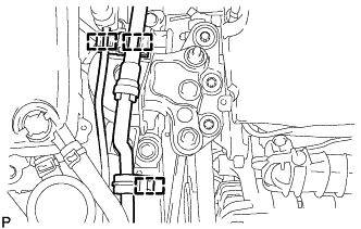
Disconnect the 4 connectors from the glow plug assemblies.
-
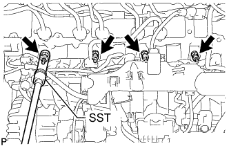
Using SST, remove the 4 glow plug assemblies.
SST PZ4TB-04910-68
-
- Click here
REMOVE CYLINDER HEAD SUB-ASSEMBLY
-
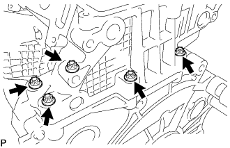
Using an E10 "TORX" socket wrench, remove the 5 bolts.
-
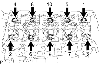
Using an E18 "TORX" socket wrench, uniformly loosen the 10 cylinder head bolts in several steps in the sequence shown in the illustration.
Note:Do not reuse the cylinder head bolt.
-
Remove the 10 cylinder head bolts and cylinder head sub-assembly.
-
- Click here
REMOVE CYLINDER HEAD GASKET