-
When replacing the injectors (including shuffling the injectors between the cylinders), common rail, intake manifold or cylinder head, it is necessary to replace the injection pipes with new ones.
-
When replacing the fuel supply pump, common rail, intake manifold or cylinder head, it is necessary to replace the fuel inlet pipe with a new one.
- Click here
PRECAUTION
Note:After turning the ignition switch off, waiting time may be required before disconnecting the cable from the battery terminal. Therefore, make sure to read the disconnecting the cable from the battery terminal notice before proceeding with work (Click here).
- Click here
DISCONNECT CABLE FROM NEGATIVE BATTERY TERMINAL
Note:When disconnecting the cable, some systems need to be initialized after the cable is reconnected (Click here).
- Click here
REMOVE NO. 1 ENGINE COVER
-
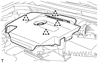
Hold the rear of the No. 1 engine cover and slowly raise it to detach the clip on the rear of the No. 1 engine cover. Continue to raise the No. 1 engine cover to detach the 3 clips on the front and side of the No. 1 engine cover and remove the No. 1 engine cover.
Note:Attempting to disengage both front and rear clips at the same time may cause the cover to break.
-
- Click here
REMOVE AIR CLEANER CAP SUB-ASSEMBLY
-
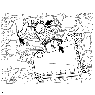
Detach the clamp and disconnect the mass air flow meter connector.
-
Slide the clamp and disconnect the PCV hose from the cylinder head cover sub-assembly.
-
Slide the clamp and disconnect the air cleaner hose assembly from the turbocharger sub-assembly.
-
Detach the 4 clamps and remove the air cleaner cap sub-assembly.
-
- Click here
REMOVE AIR CLEANER FILTER ELEMENT SUB-ASSEMBLY
- Click here
REMOVE AIR CLEANER CASE SUB-ASSEMBLY
-
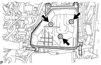
Remove the 3 bolts and air cleaner case.
-
- Click here
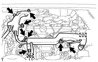
DISCONNECT ENGINE WIRE
-
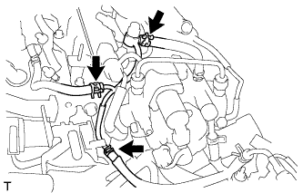
Disconnect the fuel pressure sensor connector and the pressure discharge valve connector.
-
Detach the 2 wire harness clamps.
-
Remove the bolt and wire harness bracket.
-
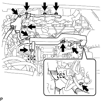
for DPF:
-
Disconnect the glow plug connector.
-
Disconnect the 3 connectors.
-
Remove the 2 bolts and 5 nuts and disconnect the engine wire.
-
-
for CCo:
Remove the screw grommet and nut, and disconnect the glow plug wire harness.
-
Remove the screw grommet and nut, and disconnect the glow plug wire harness.
-
Remove the bolt and 3 nuts, and disconnect the engine wire.
-
-
- Click here
REMOVE INJECTION PIPE SUB-ASSEMBLY
Note:After removing the injection pipe, to prevent dirt or foreign objects from entering the pipe inlet, cover the common rail with electrical tape. Also protect the injector inlets with electrical tape or plastic bags.
-
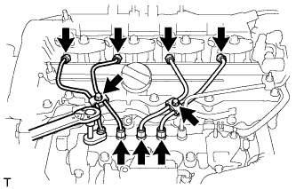
Remove the 2 bolts and 4 No. 2 injection pipe clamps.
-
Using a 14 mm union nut wrench, loosen the 4 union nuts at the common rail assembly end of the injection pipes.
-
Using a 14 mm union nut wrench, loosen the 4 union nuts at the injector assembly end of the injection pipes.
-
Remove the 4 injection pipes.
-
- Click here
REMOVE FUEL HOSE PROTECTOR (for DPF)
-
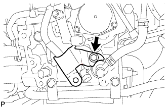
Remove the bolt and fuel hose protector.
-
- Click here
REMOVE FUEL TUBE SUB-ASSEMBLY (for DPF)
-
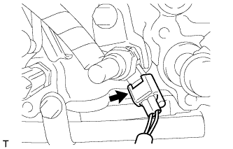
Disconnect the exhaust fuel addition injector connector.
-
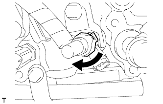
Turn the retainer as shown in the illustration.
-
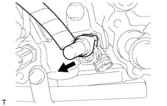
Disconnect the fuel tube sub-assembly from the exhaust fuel addition injector assembly.
-
Remove the check valve and gasket.
Table 1. Text in Illustration 
Check Valve -
Remove the union bolt, gasket and fuel tube sub-assembly.
-
- Click here
REMOVE NO. 2 FUEL PIPE (for CCo)
-
Remove the check valve and gasket.
Table 2. Text in Illustration Check Valve -
Remove the union bolt, gasket and No. 2 fuel pipe.
-
- Click here
REMOVE NO. 2 NOZZLE LEAKAGE PIPE
-
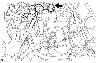
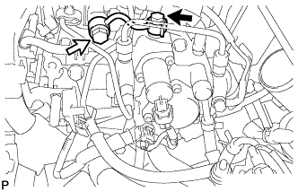
Slide the 3 clips and disconnect the 3 fuel hoses from the No. 2 fuel hose, No. 3 fuel hose and No. 4 fuel hose.
-
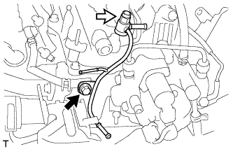
Remove the check valve and gasket.
Table 3. Text in Illustration Check Valve -
Remove the bolt and No. 2 nozzle leakage pipe.
-
- Click here
REMOVE NO. 1 NOZZLE LEAKAGE PIPE
-
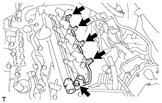
Remove the 4 union bolts and 4 gaskets.
-
Remove the bolt and No. 1 nozzle leakage pipe.
-
- Click here
REMOVE NO. 1 NOZZLE HOLDER CLAMP
-
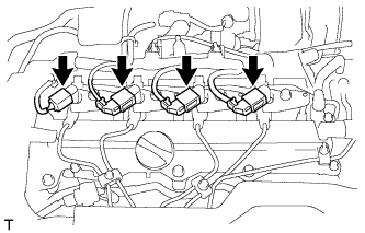
Disconnect the 4 injector connectors.
-
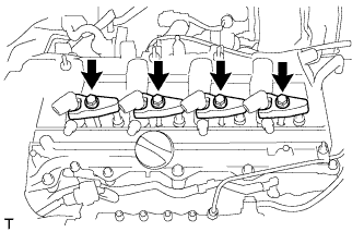
Remove the 4 bolts, 4 washers and 4 No. 1 nozzle holder clamps.
-
- Click here
REMOVE INJECTOR ASSEMBLY
-
Remove the 4 injectors and 4 injection nozzle seats from the cylinder head.
-
Remove the O-ring from each injector assembly.
Note:When removing the injector assembly, store the injectors in the correct order so that they can be returned to their original locations when reassembling.
-