ENGINE UNIT DISASSEMBLY

-
REMOVE OIL FILLER CAP SUB-ASSEMBLY
-
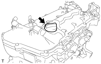
Remove the oil filler cap.
-
-
REMOVE OIL FILLER CAP GASKET
-
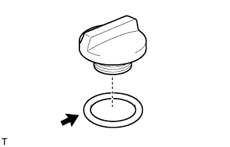
Remove the oil filler cap gasket.
-
-
REMOVE ENGINE COVER JOINT
-
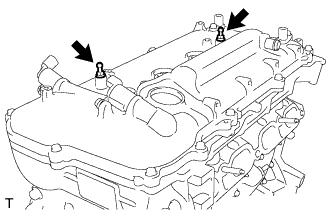
Remove the 2 engine cover joints.
-
-
REMOVE SPARK PLUG
-
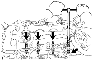
Using a 14 mm spark plug wrench and 100 mm extension bar, remove the 4 spark plugs.
-
-
REMOVE CAMSHAFT POSITION SENSOR
-
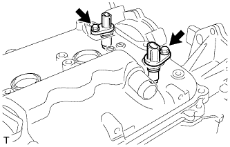
Remove the 2 bolts and 2 camshaft position sensors.
-
-
REMOVE CAMSHAFT TIMING OIL CONTROL VALVE ASSEMBLY
-
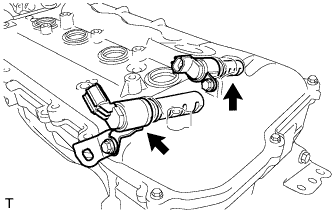
Remove the 2 bolts, wire harness bracket and 2 camshaft timing oil control valves.
-
Remove the 2 O-rings from the camshaft timing oil control valves.
-
-
REMOVE CRANKSHAFT POSITION SENSOR
-
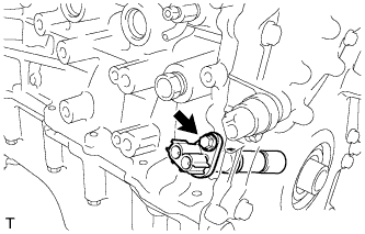
Remove the bolt and crankshaft position sensor.
-
-
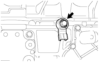
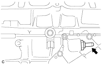
REMOVE ENGINE OIL PRESSURE SWITCH ASSEMBLY
-
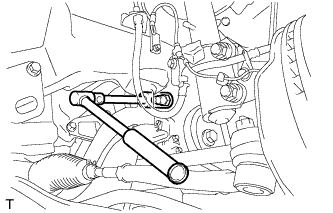
Disconnect the oil pressure switch connector.
-
Using a deep socket wrench, remove the oil pressure switch.
-
-
REMOVE KNOCK SENSOR
-
Remove the bolt and knock sensor.
-
-
REMOVE ENGINE COOLANT TEMPERATURE SENSOR
-
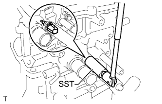
Using SST, remove the engine coolant temperature sensor and gasket.
- SST
- 09817-33190
-
-
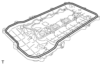
REMOVE CYLINDER HEAD COVER SUB-ASSEMBLY
-
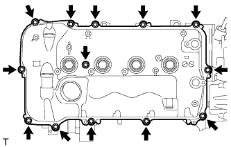
Remove the 13 bolts, seal washer and cylinder head cover.
-
Remove the 3 gaskets from the camshaft bearing cap.
Note
As gaskets may stick to the cylinder head cover, be careful not to drop any of the gaskets into the engine when removing the cylinder head cover.
-
-
REMOVE CYLINDER HEAD COVER GASKET
-
Remove the cylinder head cover gasket.
-
-
REMOVE SPARK PLUG TUBE GASKET
-
Pry up the 4 claws of the ventilation baffle plate.
Note
Do not deform the claws of the baffle plate more than necessary.
-
Remove the 4 gaskets from the cylinder head cover.
Tech Tips
Prevent the plug tube gaskets from being deformed as much as possible. The removed gaskets will be used when installing new gaskets.
Note
Be careful not to damage the cylinder head cover.
-
-
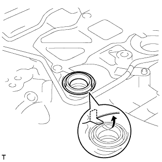
REMOVE OIL FILTER CAP ASSEMBLY
-
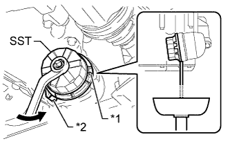
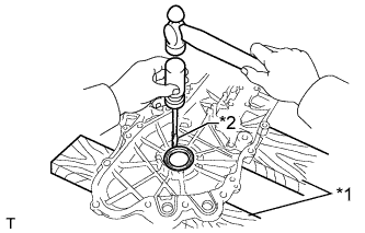
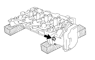
Text in Illustration *1 Cap Rid *2 Oil Filter Bracket Clip Using SST, loosen the oil filter cap 4 revolutions, align the cap ribs vertically, and drain the remaining engine oil in the oil filter cap.
- SST
- 09228-06501
Tech Tips
Set a container below the oil filter cap before loosening the oil filter cap.
Note
Do not remove the oil filter bracket clip when removing the oil filter cap.
-
Remove the oil filter cap.
-
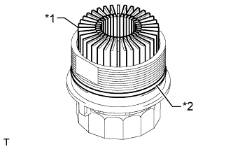
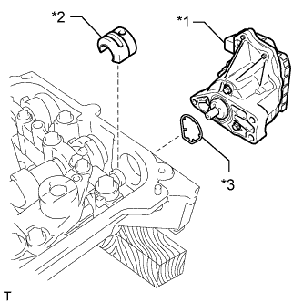
Text in Illustration *1 Oil Filter Element *2 O-Ring Remove the oil filter element and O-ring from the oil filter cap.
Note
Be sure to remove the O-ring (for the cap) by hand, without using any tools, to prevent damage to the groove for the O-ring on the cap.
-
-
SET NO. 1 CYLINDER TO TDC/COMPRESSION
-
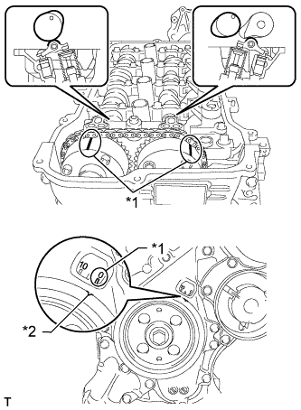
Text in Illustration *1 Timing Mark *2 Timing Notch Turn the crankshaft pulley until its notch and timing mark "0" of the timing chain cover are aligned.
-
Check that timing marks on both the camshaft timing exhaust gear and camshaft timing gear are facing upward as shown in the illustration.
Tech Tips
If not, turn the crankshaft 1 complete revolution (360°) and align the marks as above.
-
-
REMOVE CRANKSHAFT PULLEY
-
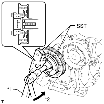
Text in Illustration *1 Hold *2 Turn Using SST, hold the crankshaft pulley and loosen the pulley bolt. Further loosen the bolt until 2 or 3 threads are screwed into the crankshaft.
for 86 mm (3.39 in.) Bolt Pitch Type:
- SST
- 09213-58014 ( 91551-80840 )
- 09330-00021
for 64 mm (2.52 in.) Bolt Pitch Type:
- SST
- 09213-54015
- 09330-00021
Tech Tips
For the 64 mm (2.52 in.) bolt pitch type, the part number of the installation bolt for SST (crankshaft pulley holding tool) is 91551-00850 (quantity: 2).
-
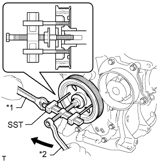
Text in Illustration *1 Hold *2 Turn Using SST and the pulley bolt, remove the crankshaft pulley and pulley bolt.
- SST
- 09950-50013 ( 09951-05010, 09952-05010, 09953-05020, 09954-05021 )
Tech Tips
Apply lubricant to the threads and end of SST.
-
-
REMOVE NO. 1 CHAIN TENSIONER ASSEMBLY
-
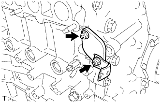
Remove the 2 nuts, bracket, chain tensioner and gasket.
Note
Do not turn the crankshaft without the No. 1 chain tensioner installed.
-
-
REMOVE TIMING CHAIN COVER SUB-ASSEMBLY
-
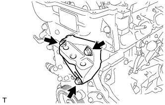
Remove the 3 bolts and engine mounting bracket.
-
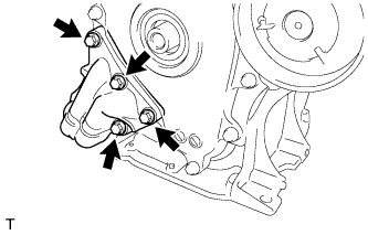
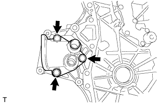
Remove the 4 bolts and oil filter bracket.
-
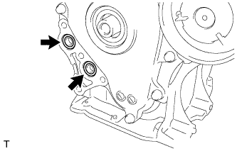
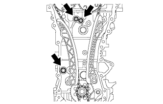
Remove the 2 O-rings.
-
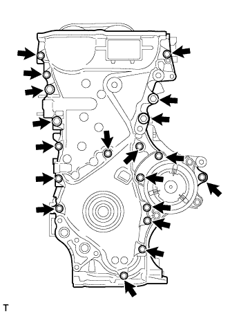
Remove the 19 bolts.
-
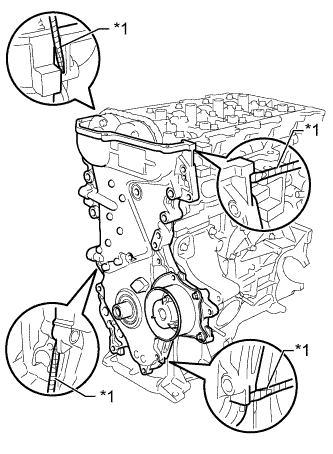
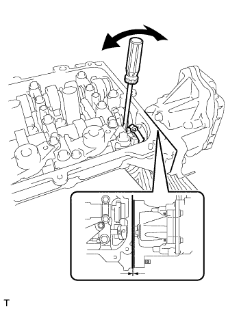
Text in Illustration *1 Protective Tape Remove the timing chain cover by prying between the timing chain cover and cylinder head, camshaft housing, cylinder block and stiffening crankcase with a screwdriver as shown in the illustration.
Tech Tips
Tape the screwdriver tip before use.
Note
Be careful not to damage the contact surfaces of the cylinder head, camshaft housing, cylinder block, stiffening crankcase and timing chain cover.
-
Remove the 3 O-rings.
-
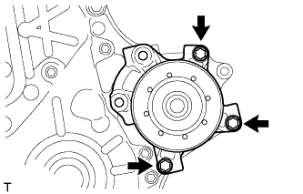
Remove the 3 bolts and water pump.
-
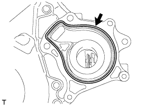
Remove the gasket.
-
-
REMOVE TIMING CHAIN COVER OIL SEAL
-
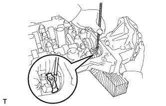
Text in Illustration *1 Wooden Block *2 Protective Tape Place the timing chain cover on wooden blocks.
-
Using a screwdriver, tap out the oil seal.
Tech Tips
Tape the screwdriver tip before use.
Note
Do not damage the surface of the oil seal press fit hole.
-
-
REMOVE ENGINE MOUNTING BRACKET STUD BOLT
Note
If a stud bolt is deformed or its threads are damaged, replace it.
-
REMOVE WATER INLET HOUSING STUD BOLT
Note
If a stud bolt is deformed or its threads are damaged, replace it.
-
REMOVE WATER INLET HOUSING
-
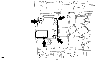
Remove the 3 bolts, water inlet housing and gasket.
-
-
REMOVE NO. 1 GENERATOR BRACKET
-
Remove the 4 bolts and generator bracket.
-
-
REMOVE CHAIN TENSIONER SLIPPER
-
Remove the chain tensioner slipper from the cylinder block.
-
-
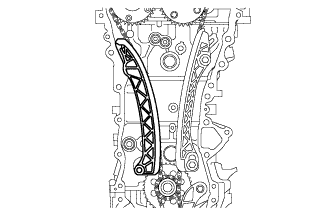
REMOVE NO. 1 CHAIN VIBRATION DAMPER
-
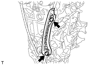
Remove the 2 bolts and chain vibration damper.
-
-
REMOVE CHAIN SUB-ASSEMBLY
-
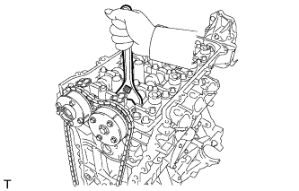
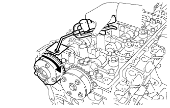
Hold the hexagonal portion of the camshaft with a wrench and turn the camshaft timing gear counterclockwise to loosen the chain between the camshaft timing gears.
-
With the chain loosened, release the chain from the camshaft timing gear and place it on the camshaft timing gear.
Tech Tips
Be sure to release the chain from the sprocket completely.
-
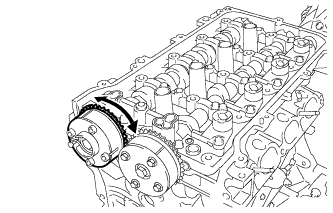
Turn the camshaft clockwise to return it to the original position and remove the chain.
-
-
REMOVE CRANKSHAFT TIMING SPROCKET
-
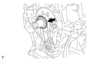
Remove the crankshaft timing sprocket.
-
-
REMOVE NO. 2 CHAIN SUB-ASSEMBLY
-
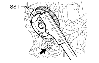
Temporarily install the crankshaft pulley and crankshaft pulley bolt.
-
Using SST, hold the crankshaft. Then remove the drive shaft gear nut.
for 86 mm (3.39 in.) Bolt Pitch Type:
- SST
- 09213-58014 ( 91551-80840 )
- 09330-00021
for 64 mm (2.52 in.) Bolt Pitch Type:
- SST
- 09213-54015
- 09330-00021
Tech Tips
For the 64 mm (2.52 in.) bolt pitch type, the part number of the installation bolt for SST (crankshaft pulley holding tool) is 91551-00850 (quantity: 2).
-
Remove SST, the crankshaft pulley bolt and crankshaft pulley.
-
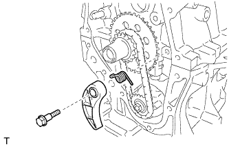
Remove the bolt, chain tensioner plate and spring.
-
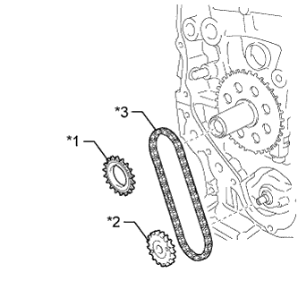
Text in Illustration *1 Oil Pump Drive Gear *2 Oil Pump Drive Shaft Gear *3 No. 2 Chain Sub-assembly Remove the oil pump drive gear, oil pump drive shaft gear and No. 2 chain.
-
-
REMOVE NO. 1 CRANKSHAFT POSITION SENSOR PLATE
-
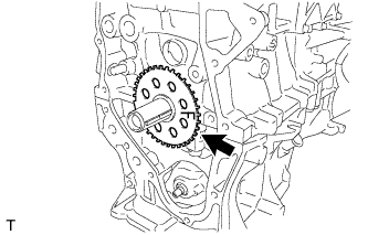
Remove the crankshaft position sensor plate.
-
-
REMOVE CRANKSHAFT TIMING GEAR KEY
-
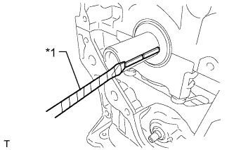
Text in Illustration *1 Protective Tape Using a screwdriver, remove the 2 crankshaft timing gear keys.
Tech Tips
Tape the screwdriver tip before use.
Note
Be careful not to damage the crankshaft.
-
-
INSPECT CAMSHAFT TIMING GEAR ASSEMBLY
-
Inspect the lock of the camshaft timing gear.
-
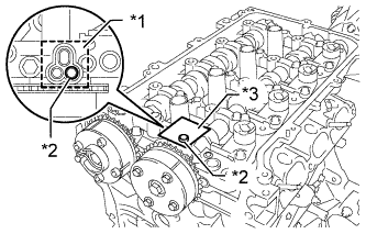
Text in Illustration *1 Adhesive Tape Sealing Area *2 Prick a Hole *3 Adhesive Tape After cleaning and degreasing the VVT oil hole on the intake side of the No. 1 camshaft bearing cap, completely seal the oil hole with adhesive tape or equivalent as shown in the illustration to prevent air from leaking.
Note
Be sure to cover the oil hole completely because air leaks due to insufficient sealing will prevent the lock pin from being released.
-
Prick a hole in the tape covering the oil hole as shown in the illustration. (Procedure A)
-
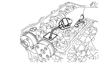
Apply approximately 150 kPa (1.5 kgf/cm2, 22 psi) of air pressure to the hole pricked in procedure A to release the lock pin.
Note
-
If air leaks out, reattach the adhesive tape.
-
Cover the oil hole with a piece of cloth when applying air pressure to prevent oil from spraying.
-
-
Forcibly turn the camshaft timing gear in the advance direction (counterclockwise).
Tech Tips
Depending on the air pressure applied, the camshaft timing gear may turn in the advance direction without assistance.
-
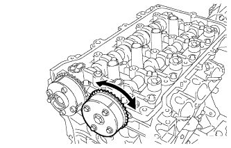
Turn the camshaft timing gear within its movable range (26.5 to 28.5°) 2 or 3 times without turning it to the most retarded position. Make sure that the camshaft timing gear turns smoothly.
-
Remove the adhesive tape from the No. 1 camshaft bearing cap.
-
-
INSPECT CAMSHAFT TIMING EXHAUST GEAR ASSEMBLY
-
Check the lock of the camshaft timing exhaust gear.
-
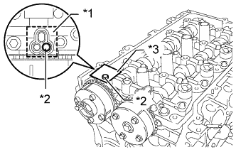
Text in Illustration *1 Adhesive Tape Sealing Area *2 Prick a Hole *3 Adhesive Tape After cleaning and degreasing the VVT oil hole on the exhaust side of the No. 1 camshaft bearing cap, completely seal the oil hole with adhesive tape or equivalent as shown in the illustration to prevent air from leaking.
Note
Be sure to cover the oil hole completely because air leaks due to insufficient sealing will prevent the lock pin from being released.
-
Prick a hole in the tape covering the oil hole as shown in the illustration. (Procedure A)
-
Apply approximately 200 kPa (2.0 kgf/cm2, 28 psi) of air pressure to the hole pricked in procedure A to release the lock pin.
Note
-
If air leaks out, reattach the adhesive tape.
-
Cover the oil hole with a piece of cloth when applying air pressure to prevent oil from spraying.
-
-
Using a screwdriver with its tip wrapped with tape, forcibly turn the camshaft timing exhaust gear in the retard direction (clockwise).
Note
-
Be sure to keep the camshaft timing exhaust gear in the retard direction using a screwdriver. If the gear is released, it will return to the most advanced position automatically due to the force from the spring.
-
Do not damage the camshaft timing exhaust gear.
-
-
Using a screwdriver with its tip wrapped with tape, turn the camshaft timing exhaust gear within its movable range (19 to 21°) 2 or 3 times without turning it to the most advanced position. Make sure that the camshaft timing exhaust gear turns smoothly.
-
Remove the adhesive tape from the No. 1 camshaft bearing cap.
-
-
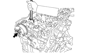
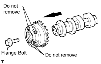
REMOVE CAMSHAFT TIMING GEAR ASSEMBLY
-
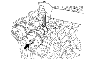
Remove the flange bolt while holding the hexagonal portion of the camshaft, and then remove the camshaft timing gear.
Note
-
Before removing the camshaft timing gear, make sure that the lock pin has been released.
-
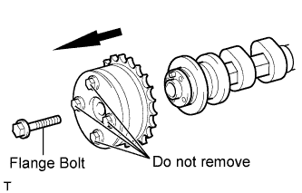
Be sure not to remove the other 4 bolts.
-
Keep the camshaft timing gear horizontal while removing it from the camshaft.
-
-
-
REMOVE CAMSHAFT TIMING EXHAUST GEAR ASSEMBLY
-
Remove the flange bolt while holding the hexagonal portion of the camshaft, and then remove the camshaft timing exhaust gear.
Note
-
Be sure not to remove the other 4 bolts.
-
Keep the camshaft timing exhaust gear horizontal while removing it from the camshaft.
-
-
-
REMOVE VALVE ROCKER ARM LOST MOTION DAMPER SUB-ASSEMBLY
-
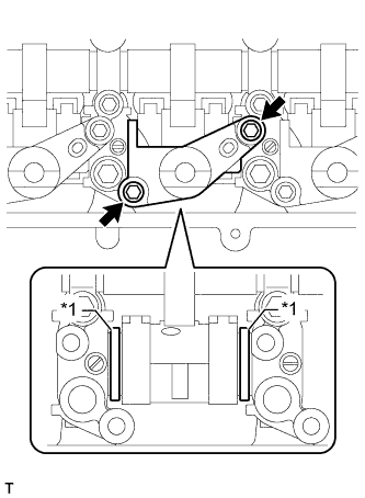
Text in Illustration *1 Shim Remove the 2 bolts and valve rocker arm lost motion damper.
Note
-
Make sure the camshaft housing is installed to the cylinder head when removing or installing a valve rocker arm lost motion damper.
-
If a valve rocker arm lost motion damper is removed, do not remove the camshaft housing.
-
Do not remove the shims. If a shim is removed, replace the camshaft housing as engine malfunctions may result from irregular valve timing.
-
-
-
INSTALL VALVE ROCKER ARM LOST MOTION DAMPER SUB-ASSEMBLY
-
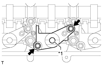
Text in Illustration *1 Hole for Engine Oil Install the valve rocker arm lost motion damper with the 2 bolts. Uniformly tighten the bolts.
- Torque:
- 10 N*m { 102 kgf*cm, 7 ft.*lbf }
-
Add engine oil into the hole for engine oil.
-
-
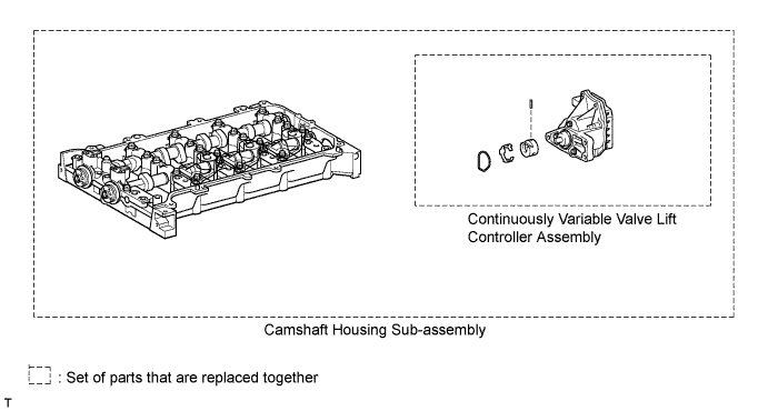
REMOVE CAMSHAFT HOUSING SUB-ASSEMBLY
Note
-
The camshaft housing is replaced with an assembled unit that includes the camshaft housing, camshafts, camshaft bearing caps, valve rocker shaft and valve rocker arm lost motion damper. Do not disassemble the camshaft housing. If disassembled, replace the camshaft housing sub-assembly.
-
The camshafts cannot be replaced by themselves.
-
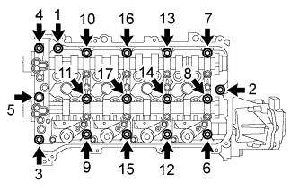
Uniformly loosen and remove the 17 bearing cap bolts in the sequence shown in the illustration.
Note
Uniformly loosen the bearing cap bolts while keeping the camshaft housing level.
-
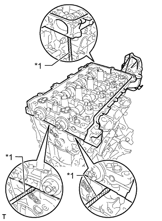
Text in Illustration *1 Protective Tape Remove the camshaft housing by prying between the cylinder head and camshaft housing with a screwdriver.
Tech Tips
Tape the screwdriver tip before use.
Note
Be careful not to damage the contact surfaces of the cylinder head and camshaft housing.
-
-
REMOVE CONTINUOUSLY VARIABLE VALVE LIFT CONTROLLER ASSEMBLY
-
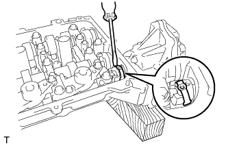
Using a screwdriver, slide the control actuator clip from the control actuator connector.
Note
Slide only the upper part of the control actuator clip, as the straight pin may fall if the control actuator clip is completely removed.
-
Remove the bolt.
-
Using a screwdriver, lightly pry the control actuator connector to make a space between the continuously variable valve lift controller and camshaft housing.
Note
-
Do not forcefully pry the control actuator connector.
-
Do not damage the camshaft housing or camshaft bearing cap.
-
-
Using a magnet hand, remove the straight pin from the control actuator connector.
Tech Tips
The straight pin can be removed by utilizing the space between the continuously variable valve lift controller and camshaft housing to move the continuously variable valve lift controller so that there is no load on the straight pin.
-
Text in Illustration *1 Continuously Variable Valve Lift Controller Assembly *2 Valve Lift Control Actuator Connector *3 O-Ring Remove the continuously variable valve lift controller from the camshaft housing.
-
Remove the O-ring from the continuously variable valve lift controller.
Note
The O-ring may remain on the camshaft housing side. Be sure to always remove it.
-
Remove the valve lift control actuator connector from the valve rocker shaft.
Tech Tips
There are two types of valve lift control actuator connectors. One type is removed by rotating the connector, and the other type can be removed without being rotated.
-
-
REMOVE CAMSHAFT HOUSING STUD BOLT
Note
If a stud bolt is deformed or its threads are damaged, replace it.
-
REMOVE CAMSHAFT HOUSING STRAIGHT PIN
Note
It is not necessary to remove a straight pin unless it is being replaced.
-
REMOVE NO. 1 VALVE ROCKER ARM SUB-ASSEMBLY
-
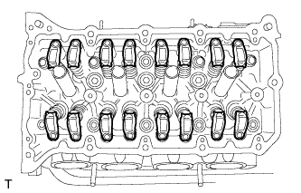
Remove the 16 valve rocker arms.
Tech Tips
Arrange the removed parts in the correct order.
-
-
REMOVE VALVE LASH ADJUSTER ASSEMBLY
-
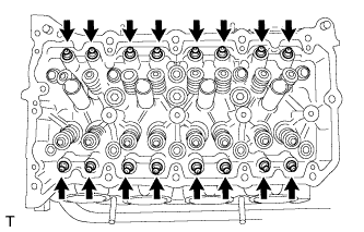
Remove the 16 valve lash adjusters from the cylinder head.
Tech Tips
Arrange the removed parts in the correct order.
-
-
REMOVE VALVE STEM CAP
-
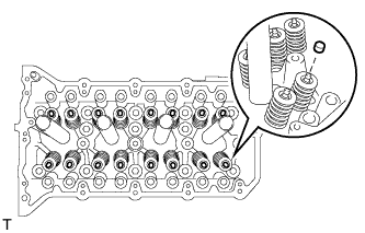
Remove the 16 valve stem caps.
Tech Tips
Arrange the removed parts in the correct order.
-
-
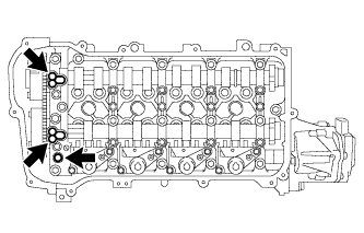
REMOVE CYLINDER HEAD SUB-ASSEMBLY
-
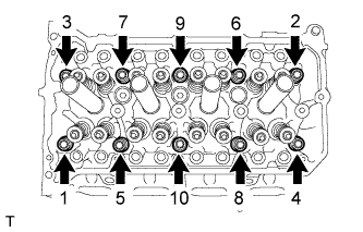
Using a 10 mm bi-hexagon wrench, uniformly loosen and remove the 10 cylinder head bolts and 10 plate washers in several steps in the sequence shown in the illustration.
Note
-
Be careful not to drop washers into the cylinder head.
-
Head warpage or cracking could result from removing the bolts in the wrong order.
-
-
Using a screwdriver with its tip wrapped with tape, pry between the cylinder head and cylinder block, and remove the cylinder head.
Note
Be careful not to damage the contact surfaces of the cylinder head and cylinder block.
-
-
REMOVE CYLINDER HEAD GASKET
-
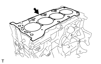
Remove the cylinder head gasket.
-
-
REMOVE VENTILATION VALVE SUB-ASSEMBLY
-
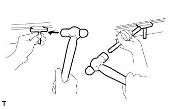
Using a 22 mm ball joint lock nut wrench, remove the ventilation valve.
-
-
REMOVE OIL PAN DRAIN PLUG
-
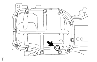
Remove the drain plug and gasket.
-
-
REMOVE NO. 2 OIL PAN SUB-ASSEMBLY
-
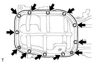
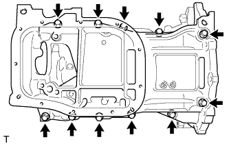
Remove the 10 bolts and 2 nuts.
-
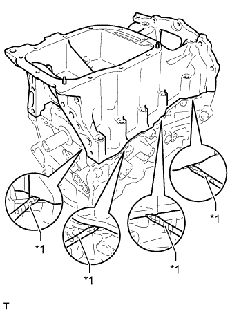
Insert the blade of an oil pan seal cutter between the crankcase and oil pan. Cut through the sealer and remove the oil pan.
Note
-
Be careful not to damage the surface of the oil pan which contacts the stiffening crankcase.
-
Be careful not to damage the stiffening crankcase flange.
-
-
-
REMOVE OIL PUMP ASSEMBLY
-
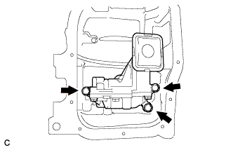
Remove the 3 bolts and oil pump.
-
-
REMOVE STIFFENING CRANKCASE ASSEMBLY
-
Uniformly loosen and remove the 11 bolts.
-
Text in Illustration *1 Protective Tape Using a screwdriver, remove the stiffening crankcase by prying between the stiffening crankcase and cylinder block.
Tech Tips
Tape the screwdriver tip before use.
Note
Be careful not to damage the contact surfaces of the crankcase and cylinder block.
-
-
REMOVE NO. 1 TAPER SCREW PLUG
-
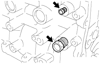
Remove the 2 No. 1 taper screw plugs.
-
-
REMOVE STIFFENING CRANKCASE STUD BOLT
Note
If a stud bolt is deformed or its threads are damaged, replace it.
-
REMOVE STIFFENING CRANKCASE RING PIN
Note
It is not necessary to remove a ring pin unless it is being replaced.
-
REMOVE ENGINE REAR OIL SEAL
-
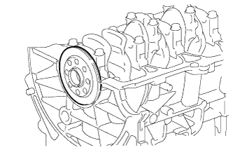
Remove the engine rear oil seal from the cylinder block.
-