ENGINE UNIT REMOVAL

-
REMOVE THROTTLE BODY ASSEMBLY
-
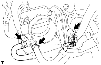
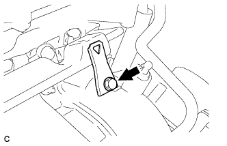
Disconnect the throttle body connector and 2 water hoses.
-
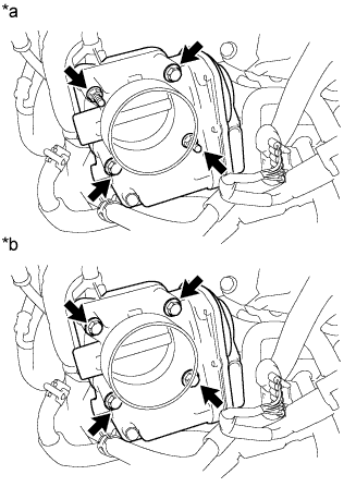
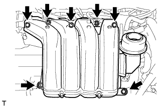
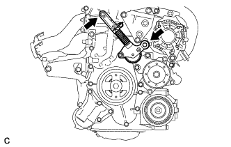
Text in Illustration *a for Type A *b for Type B for Type A:
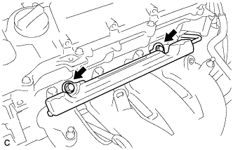
Remove the 2 bolts, 2 nuts and throttle body.
-
for Type B:
Remove the 4 bolts and throttle body.
-
Remove the gasket.
-
-
REMOVE INTAKE MANIFOLD
-
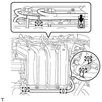
Remove the bolt and wire harness clamp bracket.
-
Detach the 5 clamps and wire harness from the intake manifold.
-
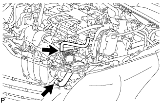
Disconnect the fuel vapor feed hose and ventilation hose.
-
Remove the 5 bolts, 2 nuts, intake manifold stay and intake manifold.
-
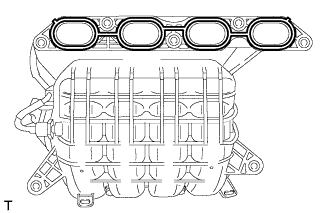
Remove the gasket from the intake manifold.
-
Remove the bolt and wire harness clamp bracket from the intake manifold.
-
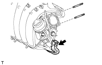
w/ Stud Bolt:
Using an E6 "TORX" socket wrench, remove the 2 stud bolts from the intake manifold.
-
-
REMOVE AIR TUBE
-
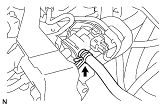
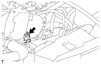
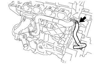
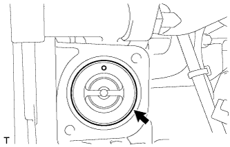
Disconnect the fuel vapor feed hose from the purge VSV.
-
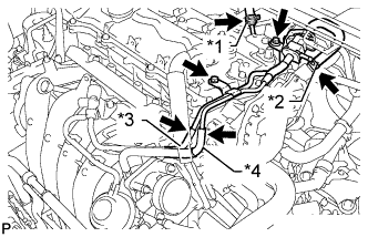
Text in Illustration *1 Union To Connector Tube Hose *2 Vacuum Hose *3 No. 2 Air Hose *4 No. 1 Fuel Vapor Feed Hose Disconnect the union to connector tube hose and vacuum hose.
-
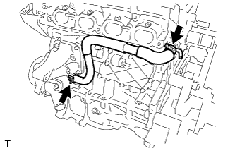
Disconnect the No. 2 air hose and No. 1 fuel vapor feed hose.
-
Remove the 2 bolts and air tube.
-
-
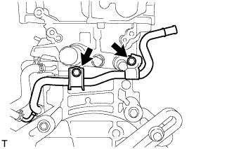
REMOVE WIRE HARNESS CLAMP BRACKET
-
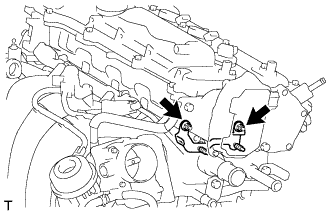
Remove the 2 nuts and wire harness clamp bracket.
-
-
REMOVE FUEL TUBE SUB-ASSEMBLY
-
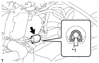
Text in Illustration *1 Claw Remove the No. 2 fuel pipe clamp.
-
Wipe off any dirt on the fuel tube connector.
-
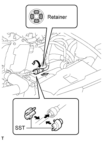
Hold the fuel tube connector and install SST.
- SST
- 09268-21010
-
Turn SST to align the retainer inside the fuel tube connector with the chamfered part of SST.
-
Insert SST into the fuel tube and hold it. Then push the fuel tube connector toward SST.
-
Mount the retainer of the fuel tube connector onto the chamfered part of SST.
-
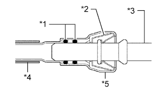
Text in Illustration *1 O-Ring *2 Retainer *3 Pipe *4 Nylon Tube *5 Fuel Tube Connector Slide SST and the fuel tube connector together towards the fuel tube until they make a "click" sound, and then disconnect the fuel tube.
-
Drain the fuel remaining inside the fuel tube.
-
Cover the fuel tube and fuel pipe with a plastic bag to protect the disconnected parts.
-
-
REMOVE FUEL DELIVERY PIPE SUB-ASSEMBLY
-
Remove the bolt and wire harness bracket.
-
Remove the 2 bolts.
-
Remove the bolt and fuel delivery pipe.
-
Remove the 2 No. 1 delivery pipe spacers.
-
-
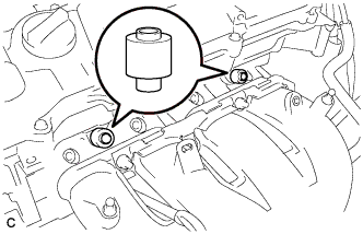
REMOVE FUEL INJECTOR ASSEMBLY
-
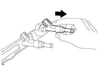
Pull the 4 fuel injector assemblies out of the fuel delivery pipe.
-
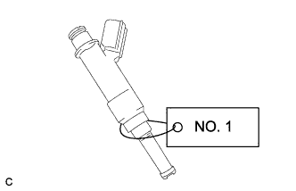
For reinstallation, attach a tag or label to the injector shaft.
Note
Prevent entry of foreign objects by covering the fuel injector with plastic bags.
-
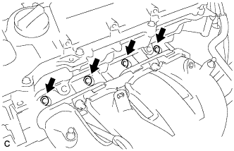
Remove the 4 injector vibration insulators.
-
-
REMOVE ENGINE OIL LEVEL DIPSTICK GUIDE
-
Remove the engine oil level dipstick.
-
Remove the bolt and dipstick guide.
-
Remove the O-ring from the dipstick guide.
-
-
REMOVE NO. 1 EXHAUST MANIFOLD HEAT INSULATOR
-
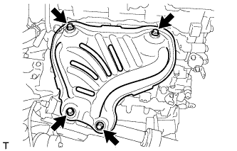
Remove the 4 bolts and No. 1 exhaust manifold heat insulator.
-
-
REMOVE DRIVE SHAFT HEAT INSULATOR SUB-ASSEMBLY
-
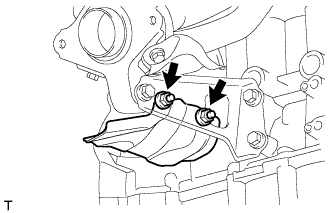
Remove the 2 nuts and drive shaft heat insulator sub-assembly.
-
-
REMOVE MANIFOLD STAY
-
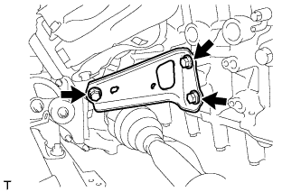
Remove the 3 bolts and manifold stay.
-
-
REMOVE EXHAUST MANIFOLD
-
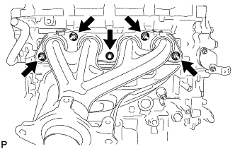
Remove the 5 nuts and exhaust manifold.
-
Remove the exhaust manifold gasket.
-
-
REMOVE NO. 1 IDLER PULLEY SUB-ASSEMBLY (w/o Air Conditioning System)
-
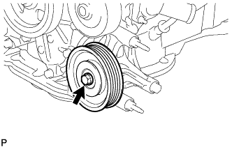
Remove the bolt, 2 idler pulley cover plates and No. 1 idler pulley sub-assembly.
-
-
REMOVE IDLER PULLEY BRACKET (w/o Air Conditioning System)
-
Remove the 2 nuts, bolt and idler pulley bracket.
-
-
REMOVE VENTILATION HOSE
-
Remove the ventilation hose from the ventilation valve.
-
-
DISCONNECT NO. 3 WATER BY-PASS HOSE
-
Disconnect the No. 3 water by-pass hose from the water inlet housing.
-
-
REMOVE WATER BY-PASS HOSE
-
Remove the clamp and water by-pass hose.
-
-
REMOVE WATER INLET HOSE
-
Remove the 2 clamps and water inlet hose.
-
-
REMOVE NO. 1 WATER BY-PASS PIPE
-
Remove the 2 bolts and water by-pass pipe.
-
-
REMOVE WATER INLET
-
Remove the 2 nuts and water inlet.
-
-
REMOVE THERMOSTAT
-
Remove the thermostat.
-
Remove the gasket from the thermostat.
-
-
REMOVE IGNITION COIL ASSEMBLY
-
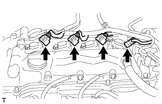
Disconnect the 4 ignition coil connectors.
-
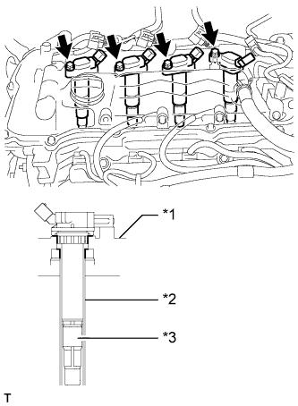
Text in Illustration *1 Cylinder Head Cover *2 Spark Plug Tube *3 Plug Cap Remove the 4 bolts and 4 ignition coils.
Note
When removing the ignition coil, do not damage the plug cap with the cylinder head cover opening or the upper edge of the spark plug tube.
-
-
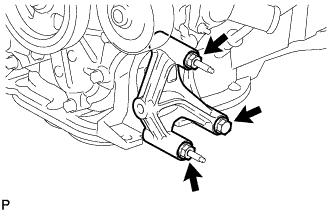
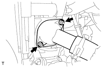
REMOVE VACUUM PUMP ASSEMBLY
-
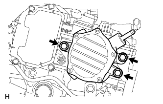
Remove the 3 bolts and vacuum pump from the engine.
-
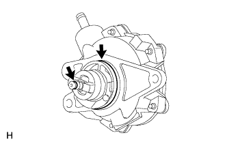
Remove the 2 O-rings from the vacuum pump.
-
-
REMOVE NO. 1 VACUUM PUMP BRACKET
-
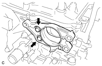
Remove the 2 bolts, vacuum pump bracket and gasket.
-
-
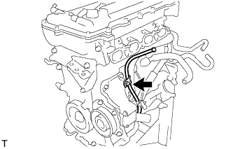
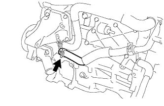
REMOVE ENGINE OIL TEMPERATURE SENSOR
-
Disconnect the engine oil temperature sensor connector.
-
Using a 19 mm deep socket wrench, remove the engine oil temperature sensor from the timing chain cover sub-assembly.
Note
If an engine oil temperature sensor has been struck or dropped, replace it.
-
Remove the gasket from the engine oil temperature sensor.
-
-
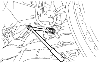
REMOVE V-RIBBED BELT TENSIONER ASSEMBLY
-
Rotate the V-ribbed belt tensioner assembly clockwise and remove the 5 mm hexagon wrench that was used to secure the V-ribbed belt tensioner assembly when removing the V-ribbed belt.
-
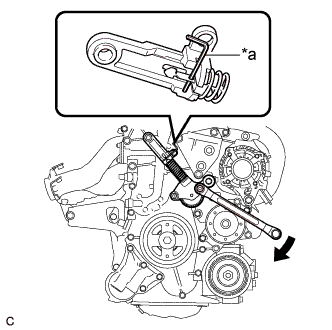
Text in Illustration *a 3 mm Hexagon Wrench Rotate the V-ribbed belt tensioner assembly slightly clockwise and secure it using a 3 mm hexagon wrench as shown in the illustration.
Tech Tips
It is difficult to install the V-ribbed belt tensioner assembly when it is fully extended. When reusing the V-ribbed belt tensioner assembly, compress and secure the V-ribbed belt tensioner assembly before removing it.
-
Remove the 2 bolts and V-ribbed belt tensioner assembly from the engine assembly.
-