ENGINE ON-VEHICLE INSPECTION

Tech Tips
The type of ignition switch used on this model differs according to the specifications of the vehicle. For the expressions listed in this section, refer to the "Ignition Switch Expressions" precaution Click here.
-
INSPECT ENGINE COOLANT
-
The engine coolant should be between the LOW and FULL lines when the engine is cold.
If the engine coolant is below the LOW line, check for leakage and add TOYOTA Super Long Life Coolant (SLLC) or similar high quality ethylene glycol based non-silicate, non-amine, non-nitrite, non-borate coolant with long-life hybrid organic acid technology to the FULL line.
-
-
INSPECT ENGINE OIL
-
Warm up the engine, and then stop the engine and wait for 5 minutes.
-
Check that the oil level is between the dipstick low level mark and full level mark.
If the level is low, check for leakage and add oil up to the full level mark.
Note
Do not fill with engine oil above the full level mark.
-
-
INSPECT BATTERY
-
Check the battery for damage, deformation and leakage.
If damage, deformation or leakage is found, replace the battery.
-
Check the electrolyte quantity of each cell.
Tech Tips
Before checking the battery voltage, turn off all the electrical systems (headlights, blower motor, rear defogger, etc.).
-
If the electrolyte quantity is below the lower line, replace the battery.
-
If the electrolyte quantity is above the lower line, check the battery voltage when cranking the engine. If the voltage is below 9.6 V, recharge or replace the battery.
-
-
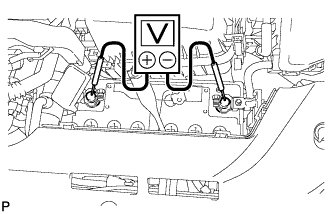
Check the voltage.
-
Turn the ignition switch off and turn on the headlights for 20 to 30 seconds. This will remove the surface charge from the battery.
-
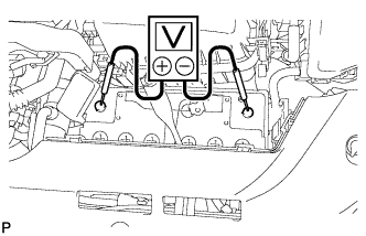
Measure the voltage according to the value(s) in the table below.
Standard Voltage Tester Connection Condition Specified Condition Positive (+) terminal - Negative (-) terminal 20°C (68°F) 12.5 to 12.9 V If the result is not as specified, charge the battery.
-
-
-
INSPECT AIR CLEANER FILTER ELEMENT SUB-ASSEMBLY
-
Remove the air cleaner cap.
-
Remove the air filter element.
-
Visually check that the air filter is not excessively damaged or oily.
If necessary, replace the air cleaner filter element.
-
-
INSPECT SPARK PLUG
Note
-
Do not use a wire brush for cleaning.
-
Do not attempt to adjust the electrode gap of a used spark plug.
-
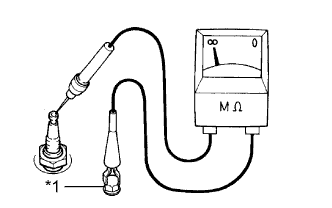
Text in Illustration *1 Ground Check the electrode.
-
Using a megohmmeter, measure the insulation resistance.
Standard resistance 10 MΩ or higher If the result is not as specified, clean the spark plug with a spark plug cleaner and measure the resistance again.
Tech Tips
If a megohmmeter is not available, perform the following simple inspection instead.
-
-
Alternative inspection method:
-
Quickly accelerate the engine to 4000 rpm 5 times.
-
Remove the spark plug.
-
Visually check the spark plug.
If the electrode is dry, the spark plug is functioning properly. If the electrode is damp, proceed to the next step.
-
-
Check the spark plug for any damage to its thread and insulator.
If there is any damage, replace the spark plug.
Recommended Spark Plug Manufacturer Product DENSO SC20HR11 -
Reference:
-
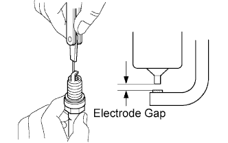
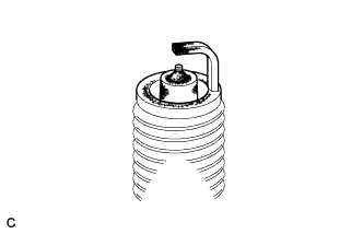
Check the spark plug electrode gap.
Maximum electrode gap for used spark plug 1.3 mm (0.0512 in.) If the gap is more than the maximum, replace the spark plug.
Electrode gap for new spark plug 1.0 to 1.1 mm (0.0394 to 0.0433 in.)
-
-
Clean the spark plug.
If the electrode has traces of wet carbon, clean the electrode with a spark plug cleaner, and then dry it.
Air pressure 588 kPa (6 kgf/cm2, 85 psi) Duration 20 seconds or less Tech Tips
Only use the spark plug cleaner when the electrode is free of oil. If the electrode has traces of oil, use gasoline to clean off the oil before using the spark plug cleaner.
-
-
INSPECT V-RIBBED BELT
-

Check the belt for wear, cracks or other signs of damage.
If any of the following defects is found, replace the V-ribbed belt.
-
The belt is cracked.
-
The belt is worn out to the extent that the cords are exposed.
-
The belt has chunks missing from the ribs.
-
-
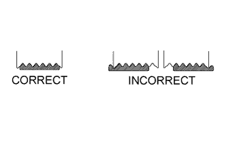
Check that the belt fits properly in the ribbed grooves.
Tech Tips
Check with your hand to confirm that the belt has not slipped out of the grooves on the bottom to the pulley. If it has slipped out, replace the V-ribbed belt. Install a new V-ribbed belt correctly.
-
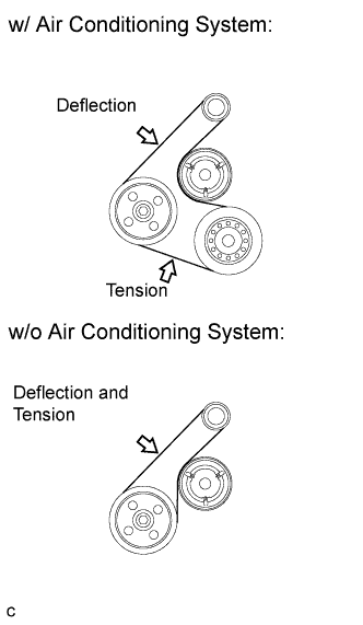
Check the V-ribbed belt deflection and tension.
Standard Deflection Item Specified Condition New belt 7.0 to 8.2 mm (0.276 to 0.323 in.) Used belt 7.6 to 10.0 mm (0.299 to 0.394 in.) Standard Tension Item Specified Condition New belt 700 to 800 N (70 to 80 kgf, 157.4 to 179.8 lbf) Used belt 550 to 750 N (55 to 75 kgf, 123.6 to 168.6 lbf) Tech Tips
-
When inspecting the V-ribbed belt deflection, apply 98 N (10 kgf, 22.0 lbf) of tensile force to it.
-
Check the V-ribbed belt deflection at the specified point.
-
V-ribbed belt tension and deflection should be checked after 2 revolutions of engine cranking.
-
Measure the belt tension when the engine is cold.
-
When adjusting the belt, be sure to adjust it so that the tension is as close as possible to the median of the specified range.
-
When replacing the belt with a new one, be sure to perform the following after adjusting the belt: idle the engine for 5 minutes, and then adjust the belt to the specified value for a new belt after the engine has cooled.
-
When inspecting a belt which has been used for over 5 minutes, apply the used belt specifications.
-
When using a belt tension gauge, confirm its accuracy by using a master gauge first.
-
-
-
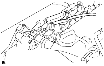
INSPECT VALVE LASH ADJUSTER NOISE
-
Rev up the engine several times. Check that the engine does not emit unusual noises.
If unusual noises occur, warm up the engine and idle it for over 30 minutes. Then perform the inspection above again.
If any defects or problems are found during the inspection above, perform a lash adjuster inspection Click here.
-
-
INSPECT IGNITION TIMING
-
Warm up and stop the engine.
-
When using an intelligent tester:
-
Connect the intelligent tester to the DLC3.
-
Start the engine and idle it.
-
Turn the intelligent tester main switch on.
-
Enter the following menus: Powertrain / Engine and ECT / Data List / IGN Advance.
Standard ignition timing 0 to 14° BTDC @ idle Tech Tips
Refer to the intelligent tester operator's manual for further details.
Note
-
Turn all the electrical systems and the A/C off.
-
Check the ignition timing with the cooling fan off.
-
When checking the ignition timing, the shift lever should be in neutral.
-
-
Enter the following menus: Powertrain / Engine and ECT / Active Test / Connect the TC and TE1.
-
Monitor IGN Advance of the Data List.
Standard ignition timing 8 to 12° BTDC @ idle Tech Tips
Refer to the intelligent tester operator's manual for further details.
Note
-
Turn all the electrical systems and the A/C off.
-
Check the ignition timing with the cooling fan off.
-
When checking the ignition timing, the shift lever should be in neutral.
-
-
Check that the ignition timing advances immediately when the engine speed is increased.
-
Turn the ignition switch off.
-
Disconnect the intelligent tester from the DLC3.
-
-
When not using the intelligent tester:
-
Remove the No. 2 cylinder head cover.
-
Connect the tester probe of a timing light to the wire of the ignition coil connector for the No. 1 cylinder.
Note
Use a timing light that detects primary signals.
-
Start the engine and idle it.
-
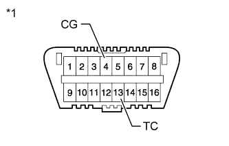
Text in Illustration *1 Front View of DLC3 Using SST, connect terminals 13 (TC) and 4 (CG) of the DLC3.
- SST
- 09843-18040
Note
-
Confirm the terminal numbers before connecting them. Connecting the wrong terminals can damage the engine.
-
When checking the ignition timing, the shift lever should be in neutral.
-
Using the timing light, check the ignition timing.
Standard ignition timing 8 to 12° BTDC @ idle Note
-
Turn all the electrical systems and the A/C off.
-
Check the ignition timing with the cooling fan off.
-
When checking the ignition timing, the shift lever should be in neutral.
-
-
Remove SST from the DLC3.
-
Inspect the ignition timing at idle.
Standard ignition timing 0 to 14° BTDC @ idle Note
-
Turn all the electrical systems and the A/C off.
-
Check the ignition timing with the cooling fan off.
-
When checking the ignition timing, the shift lever should be in neutral.
-
-
Check that the ignition timing advances immediately when the engine speed is increased.
-
Turn the ignition switch off.
-
Remove the timing light.
-
Install the No. 2 cylinder head cover.
-
-
-
INSPECT ENGINE IDLE SPEED
-
Warm up and stop the engine.
-
When using the intelligent tester:
-
Connect the intelligent tester to the DLC3.
-
Turn the ignition switch to ON.
-
Enter the following menus: Powertrain / Engine and ECT / Data List / Engine Speed.
Standard idle speed 580 to 680 rpm Tech Tips
Refer to the intelligent tester operator's manual for further details.
Note
-
Turn all the electrical systems and the A/C off.
-
Check the ignition timing with the cooling fan off.
-
When checking the idling speed, the shift lever should be in neutral.
-
-
-
Turn the ignition switch off.
-
Disconnect the intelligent tester from the DLC3.
-
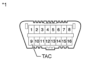
Text in Illustration *1 Front View of DLC3 When not using the intelligent tester:
-
Using SST, connect a tachometer probe to terminal 9 (TAC) of the DLC3.
- SST
- 09843-18030
Note
-
Confirm the terminal numbers before connecting them. Connecting the wrong terminals can damage the engine.
-
When checking the idling speed, the shift lever should be in neutral.
-
Check the idle speed.
Standard idle speed 580 to 680 rpm -
Disconnect the tachometer probe from the DLC3.
-
-
-
INSPECT COMPRESSION
-
Warm up and stop the engine.
-
Check for DTCs Click here.
-
Remove the 4 spark plugs Click here.
-
Disconnect the 4 fuel injector connectors.
-
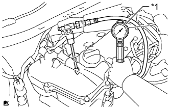
Text in Illustration *1 Compression Gauge Inspect the cylinder compression pressure.
-
Insert a compression gauge into the spark plug hole.
-
Fully open the throttle.
-
While cranking the engine, measure the compression pressure.
Standard compression pressure 1373 kPa (14.0 kgf/cm2, 199 psi) or higher Minimum pressure 1079 kPa (11.0 kgf/cm2, 156 psi) Difference between each cylinder 98 kPa (1.0 kgf/cm2, 14.2 psi) or less CAUTION:
Wear protective gloves when measuring the compression to avoid injuring your hands on the outer cowl top panel.
Note
-
Use a fully-charged battery so the engine speed can be increased to 250 rpm or more.
-
Inspect the other cylinders in the same way.
-
Measure the compression in as short a time as possible.
-
-
If the cylinder compression is low, pour a small amount of engine oil into the cylinder through the spark plug hole, and then inspect it again.
Tech Tips
-
If adding oil increases the compression, the piston rings and/or cylinder bore may be worn or damaged.
-
If the pressure stays low, the valve may be stuck or seated improperly, or there may be leakage from the gasket.
-
-
-
Connect the 4 fuel injector connectors.
-
Install the 4 spark plugs Click here.
-
Clear the DTCs Click here.
-
-
INSPECT CO/HC
-
Start the engine.
-
Run the engine at 2500 rpm for approximately 180 seconds.
-
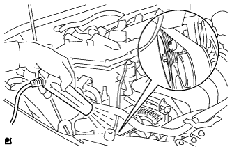
Insert the CO/HC meter testing probe at least 40 cm (1.31 ft.) into the tailpipe while idling.
-
Check the CO/HC concentration during idling and when the engine is running at 2500 rpm.
Tech Tips
When doing the 2 mode (with the engine idling/ running at 2500 rpm) test, the measuring procedures are determined by applicable local regulations.
If the CO/HC concentration does not comply with the regulations, troubleshoot in the order given below.
-
Check the air fuel ratio sensor Click here and heated oxygen sensor operation Click here.
-
See the table below for possible causes, and then inspect the applicable parts and repair them if necessary.
CO HC Problems Possible Causes Normal High Rough idling
-
Faulty ignition:
-
Incorrect timing
-
Plugs are contaminated or shorted, or gaps are defective
-
Incorrect valve clearance
-
Leakage from intake or exhaust valves
-
Leakage from cylinders
Low High Rough idling
(Fluctuating HC reading)
-
Vacuum leaks:
-
PCV hoses
-
Intake manifold
-
Throttle body
-
Brake booster line
-
Lean mixture causing misfire
High High Rough idling
(Black smoke from exhaust)
-
Restricted air cleaner filter element
-
Plugged PCV valve
-
Faulty SFI system:
-
Faulty pressure regulator
-
Faulty engine coolant temperature sensor
-
Faulty mass air flow meter
-
Faulty ECM
-
Faulty injectors
-
Faulty throttle body
-
-
-