ENGINE UNIT INSPECTION

-
INSPECT CHAIN SUB-ASSEMBLY
-
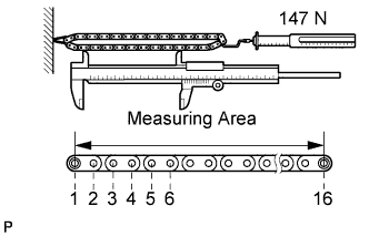
Using a spring scale, pull the chain with a force of 147 N (15 kgf, 33 lbf) as shown in the illustration.
-
Using a vernier caliper, measure the length of 16 links.
Maximum chain elongation 144.3 mm (5.68 in.) Note
Perform the measurement at 3 random places.
If the elongation is more than the maximum, replace the chain.
-
-
INSPECT NO. 1 CHAIN TENSIONER ASSEMBLY
-
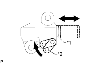
Text in Illustration *1 Plunger *2 Stopper Plate Move the stopper plate upward to release the lock. Push the plunger and check that it moves smoothly.
-
-
INSPECT CAMSHAFT TIMING SPROCKET
-
Wrap the chain around the camshaft timing sprocket.
-
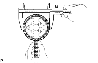
Using a vernier caliper, measure the sprocket diameter with the chain.
Minimum sprocket with chain diameter 132.6 mm (5.22 in.) Tech Tips
The vernier caliper must contact the chain rollers for the measurement.
If the diameter is less than the minimum, replace the chain sub-assembly and camshaft timing sprocket.
-
-
INSPECT CRANKSHAFT TIMING SPROCKET
-
Wrap the chain around the crankshaft timing sprocket.
-
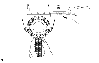
Using a vernier caliper, measure the sprocket diameter with the chain.
Minimum sprocket with chain diameter 69.1 mm (2.70 in.) Tech Tips
The vernier caliper must contact the chain rollers for the measurement.
If the diameter is less than the minimum, replace the chain sub-assembly and crankshaft timing sprocket.
-
-
INSPECT CHAIN TENSIONER SLIPPER
-
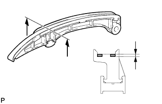
Using a vernier caliper, measure the tensioner slipper wear.
Maximum wear 1.0 mm (0.0394 in.) If the wear is more than the maximum, replace the tensioner slipper.
-
-
INSPECT NO. 1 CHAIN VIBRATION DAMPER
-
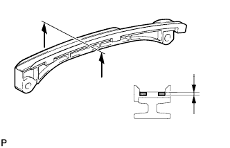
Using a vernier caliper, measure the vibration damper wear.
Maximum wear 1.0 mm (0.0394 in.) If the wear is more than the maximum, replace the vibration damper.
-
-
INSPECT INTAKE MANIFOLD
-
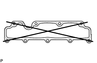
Using a precision straightedge and feeler gauge, measure the warpage of the surface where the intake manifold contacts the cylinder head.
Maximum warpage 0.10 mm (0.00394 in.) If the warpage is more than the maximum, replace the intake manifold.
-
-
INSPECT EXHAUST MANIFOLD
-
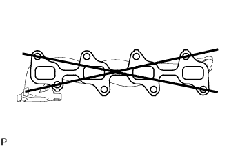
Using a precision straightedge and feeler gauge, measure the warpage of the surface where the exhaust manifold contacts the cylinder head.
Maximum warpage 0.40 mm (0.0157 in.) If the warpage is more than the maximum, replace the exhaust manifold.
-
-
INSPECT CAMSHAFT
-
Check the camshaft for runout.
-
Place the camshaft on V-blocks.
-
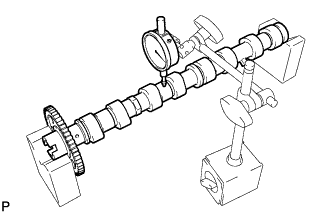
Using a dial indicator, measure the circle runout at the center journal.
Maximum circle runout 0.03 mm (0.00118 in.) If the circle runout is more than the maximum, replace the camshaft.
-
-
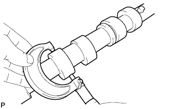
Using a micrometer, measure the cam lobe height.
Standard cam lobe height 37.559 to 37.759 mm (1.4787 to 1.4866 in.) Minimum cam lobe height 37.559 mm (1.4787 in.) If the cam lobe height is less than the minimum, replace the camshaft.
-
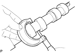
Using a micrometer, measure the journal diameter.
Standard journal diameter 26.969 to 26.985 mm (1.0618 to 1.0624 in.) If the journal diameter is not as specified, check the oil clearance.
-
-
INSPECT NO. 2 CAMSHAFT
-
Check the camshaft for runout.
-
Place the camshaft on V-blocks.
-
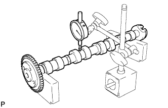
Using a dial indicator, measure the circle runout at the center journal.
Maximum circle runout 0.03 mm (0.00118 in.) If the circle runout is more than the maximum, replace the No. 2 camshaft.
-
-
Using a micrometer, measure the cam lobe height.
Standard cam lobe height 38.270 to 38.470 mm (1.5067 to 1.5146 in.) Minimum cam lobe height 38.270 mm (1.5067 in.) If the cam lobe height is less than the minimum, replace the No. 2 camshaft.
-
Using a micrometer, measure the journal diameter.
Standard journal diameter 26.969 to 26.985 mm (1.0618 to 1.0624 in.) If the journal diameter is not as specified, check the oil clearance.
-
-
INSPECT CAMSHAFT OIL CLEARANCE
-
Clean the bearing caps and camshaft journals.
-
Place the camshafts on the cylinder head.
-
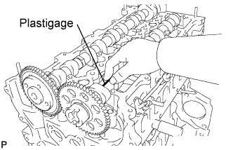
Lay a strip of Plastigage across each of the camshaft journals.
-
Install the bearing caps Click here.
Note
Do not turn the camshaft.
-
Remove the bearing caps Click here.
-
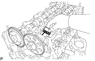
Measure the Plastigage at its widest point.
Standard oil clearance 0.025 to 0.062 mm (0.000984 to 0.00244 in.) Maximum oil clearance 0.062 mm (0.00244 in.) If the oil clearance is more than the maximum, replace the camshaft. If necessary, replace the cylinder head.
-
Completely remove the Plastigage.
-
-
INSPECT CAMSHAFT THRUST CLEARANCE
-
Install the No. 2 camshaft and camshaft Click here.
-
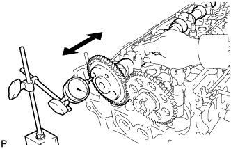
Using a dial indicator, measure the thrust clearance while moving the camshaft back and forth.
Standard thrust clearance 0.035 to 0.160 mm (0.00138 to 0.00630 in.) Maximum thrust clearance 0.160 mm (0.00630 in.) If the thrust clearance is more than the maximum, replace the cylinder head. If the thrust surface is damaged, replace the camshaft.
-
Remove the No. 2 camshaft and camshaft Click here.
-
-
INSPECT CYLINDER HEAD SET BOLT
-
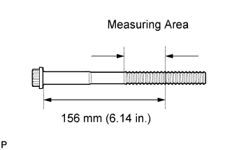
Using a vernier caliper, measure the outside diameter of the elongated thread in the measuring area.
Standard outside diameter 11.8 to 12.0 mm (0.465 to 0.472 in.) Minimum outside diameter 11.2 mm (0.441 in.) Tech Tips
If a visual check reveals no excessively thin areas, check the center of the bolt (see illustration) and find the area that has the smallest diameter.
If the diameter is less than the minimum, replace the cylinder head set bolt.
-
-
INSPECT NO. 1 OIL NOZZLE SUB-ASSEMBLY
-
Check the oil nozzle for damage or clogging.
If there is damage or clogging, replace the No. 1 oil nozzle sub-assembly.
-
-
INSPECT NO. 1 VALVE ROCKER ARM SUB-ASSEMBLY
-
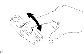
Turn the roller by hand to check that it turns smoothly.
If the roller does not turn smoothly, replace the No. 1 valve rocker arm sub-assembly.
-
-
INSPECT VALVE LASH ADJUSTER ASSEMBLY
Note
-
Keep the lash adjuster free from dirt and foreign objects.
-
Use only clean engine oil.
-
Place the lash adjuster into a container full of new engine oil.
-
Insert SST tip into the lash adjuster plunger and use the tip to press down on the check ball inside the plunger.
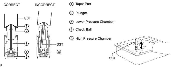
- SST
- 09276-75010
-
Squeeze SST and the lash adjuster together to move the plunger up and down 5 to 6 times.
-
Check the movement of the plunger and bleed air.
OK Plunger moves up and down. Note
When bleeding high-pressure air from the compression chamber, make sure that the tip of SST is actually pressing the check ball as shown in the illustration. If the check ball is not pressed, air will not bleed.
-
After bleeding air, remove SST. Then quickly and firmly press the plunger repeatedly with your fingers.
OK Plunger can be pressed 3 times. If the plunger can still be compressed after pressing it 3 times, replace the lash adjuster with a new one.
-
-
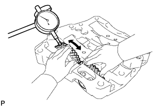
INSPECT ENGINE BALANCER ASSEMBLY THRUST CLEARANCE
-
Using a dial indicator, measure the thrust clearance while moving the balance shaft back and forth.
Standard thrust clearance 0.07 to 0.11 mm (0.00303 to 0.00433 in.) Maximum thrust clearance 0.11 mm (0.00433 in.) If the thrust clearance is more than the maximum, replace the engine balancer assembly.
-
-
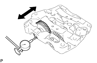
INSPECT ENGINE BALANCER ASSEMBLY BACKLASH
-
Fix the No. 3 balance shaft driven gear in place, and then using a dial indicator, measure the backlash of the No. 1 and No. 3 balance shaft driven gears as shown in the illustration.
Standard backlash 0.020 to 0.092 mm (0.000787 to 0.00362 in.) Maximum backlash 0.0114 mm (0.00449 in.) If the backlash is more than the maximum, replace the engine balancer assembly.
-