ENGINE UNIT REMOVAL

Note
-
When replacing the injectors (including shuffling the injectors between the cylinders), common rail, intake manifold or cylinder head, it is necessary to replace the injection pipes with new ones.
-
When replacing the fuel supply pump, common rail, intake manifold or cylinder head, it is necessary to replace the fuel inlet pipe with a new one.
-
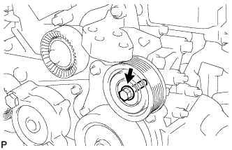
REMOVE FAN AND GENERATOR V BELT
-
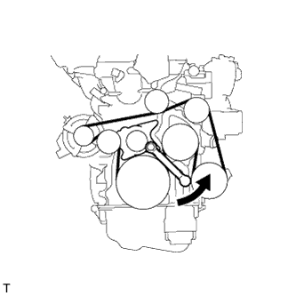
Using a 22 mm wrench, rotate the tensioner pulley counterclockwise to loosen the belt tension. Then remove the belt.
CAUTION:
-
Be careful as the wrench only fits loosely on the belt tensioner tool set point. The wrench may come off the set point and cause injuries.
-
Be careful that your hands do not become jammed between parts such as the belt, pulleys, etc.
-
-
-
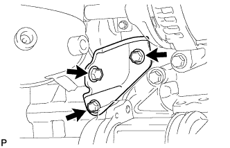
REMOVE COMPRESSOR WITH PULLEY ASSEMBLY
-
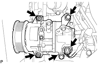
Disconnect the connector.
-
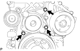
Remove the 2 bolts and 2 nuts.
-
Remove the 2 stud bolts and compressor with pulley.
-
-
REMOVE COMPRESSOR STAY
-
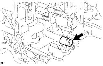
Remove the compressor stay from the cylinder block.
-
-
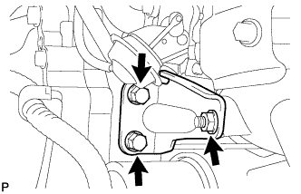
REMOVE GENERATOR ASSEMBLY
-
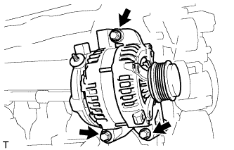
Remove the 3 bolts and generator.
-
-
REMOVE NO. 2 IDLER PULLEY SUB-ASSEMBLY
-
Remove the bolt, plate and No. 2 idler pulley.
-
-
REMOVE IDLER PULLEY COVER PLATE
-
Using a screwdriver, remove the idler pulley cover plate.
-
-
REMOVE NO. 1 IDLER PULLEY SUB-ASSEMBLY
-
Remove the bolt and No. 1 idler pulley.
-
-
REMOVE NO. 4 WATER BY-PASS PIPE
-
Remove the bolt, No. 4 water by-pass pipe and O-ring.
-
-
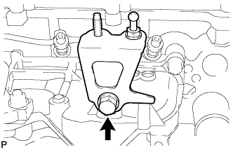
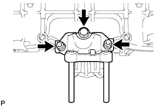
REMOVE ENGINE MOUNTING BRACKET
-
Remove the stud bolt from the engine mounting bracket.
-
Remove the 4 bolts, 2 nuts and engine mounting bracket.
-
-
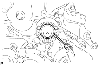
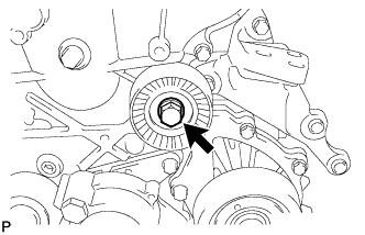
REMOVE V-RIBBED BELT TENSIONER ASSEMBLY
-
Remove the 3 bolts and V-ribbed belt tensioner.
Note
As the bolt heads are not as thick as typical bolts, be careful not to damage them during removal.
-
-
REMOVE VACUUM PUMP ASSEMBLY
-
Disconnect the vacuum hose.
-
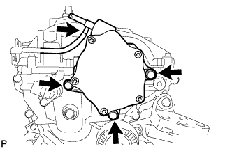
Remove the 3 bolts and vacuum pump.
-
Remove the 2 O-rings from the vacuum pump.
-
-
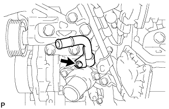
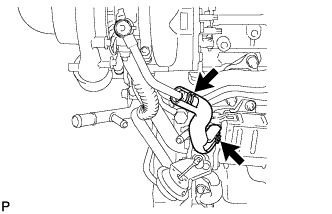
REMOVE DIESEL THROTTLE BODY ASSEMBLY
-
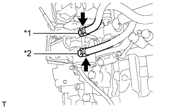
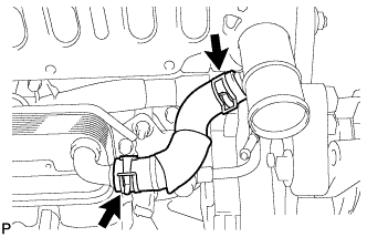
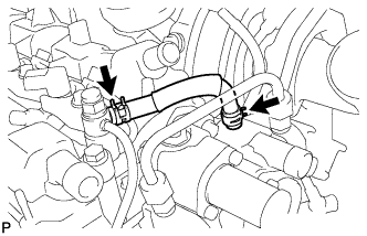
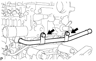
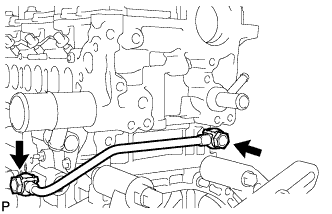
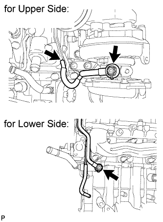
Text in Illustration *1 No. 6 Water By-pass Hose *2 No. 7 Water By-pass Hose Disconnect the No. 6 and No. 7 water by-pass hoses.
-
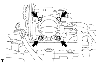
Remove the 2 bolts, 2 nuts, diesel throttle body and gasket.
-
-
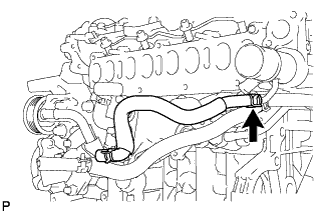
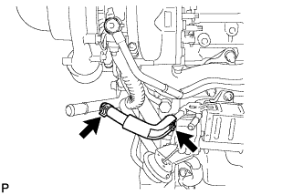
REMOVE NO. 7 WATER BY-PASS HOSE
-
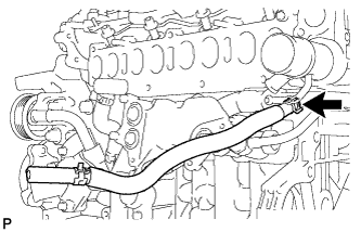
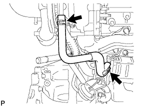
DISCONNECT NO. 8 WATER BY-PASS HOSE
-
REMOVE EGR VALVE BRACKET
-
Remove the 3 bolts and 2 brackets.
-
-
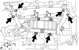
REMOVE NO. 2 EGR PIPE SUB-ASSEMBLY
-
Disconnect the electric EGR control valve connector.
-
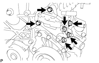
Text in Illustration *1 Nut Remove the 3 bolts, 2 nuts, No. 2 EGR pipe and 2 gaskets.
-
-
REMOVE ELECTRIC EGR CONTROL VALVE ASSEMBLY
-
Remove the electric EGR control valve and gasket.
-
-
REMOVE ENGINE OIL LEVEL DIPSTICK GUIDE
-
Remove the engine oil level dipstick.
-
Remove the 2 bolts and engine oil level dipstick guide.
-
Remove the O-ring from the engine oil level dipstick guide.
-
-
REMOVE FUEL INLET PIPE SUB-ASSEMBLY
Note
After removing the fuel inlet pipe, cover the common rail and supply pump with electrical tape to prevent dirt from entering them.
-
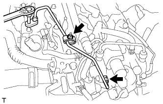
Remove the nut and 2 clamps.
-
Using a 14 mm union nut wrench, remove the fuel inlet pipe.
-
-
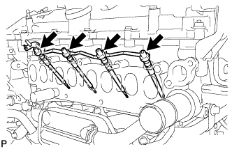
REMOVE INJECTION PIPE
Note
After removing the injection pipe, to prevent dirt or foreign objects from entering the pipe inlet, cover the common rail with electrical tape. Also protect the injector inlets with electrical tape or plastic bags.
-
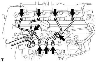
Remove the 2 bolts and 4 injection pipe clamps.
-
Using a 14 mm union nut wrench, loosen the 4 nuts at the common rail end of the injection pipes.
-
Using a 14 mm union nut wrench, loosen the 4 nuts at the injector end of the injection pipes.
-
Remove the 4 injection pipes.
-
-
REMOVE NO. 4 FUEL HOSE
-
REMOVE COMMON RAIL ASSEMBLY
-
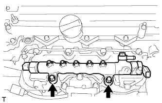
Remove the 2 bolts and common rail.
-
-
REMOVE INTAKE MANIFOLD INSULATOR
-
Remove the intake manifold insulator from the intake manifold.
-
-
REMOVE DIESEL TURBO PRESSURE SENSOR
-
Disconnect the vacuum hose.
-
Remove the bolt and sensor.
-
-
REMOVE NO. 1 GAS FILTER
-
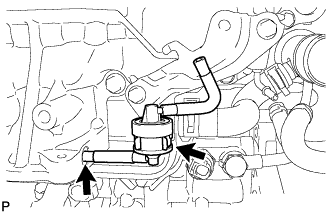
Disconnect the vacuum hose.
-
Remove the No. 1 gas filter from the gas filter bracket.
-
-
REMOVE GAS FILTER BRACKET
-
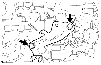
Remove the 2 bolts and gas filter bracket.
-
-
REMOVE ENGINE COVER BRACKET
-
Remove the bolt and engine cover bracket.
-
-
REMOVE NO. 2 INTAKE MANIFOLD
-
Remove the bolt, 2 nuts, No. 2 intake manifold and gasket.
-
-
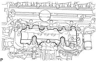
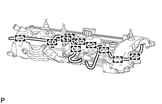
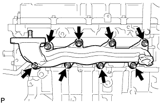
REMOVE INTAKE MANIFOLD
-
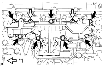
Text in Illustration *1 Nut Remove the 7 bolts, 2 nuts, intake manifold and gasket.
-
-
REMOVE GLOW PLUG ASSEMBLY
-
Remove the 4 grommets.
-
Remove the 4 nuts and No. 1 glow plug connector.
-
Using a 10 mm deep socket wrench, remove the 4 glow plugs.
-
-
REMOVE NO. 1 CYLINDER BLOCK INSULATOR
-
Remove the No. 1 cylinder block insulator from the cylinder block.
-
-
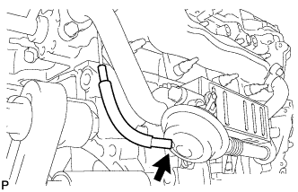
REMOVE WATER BY-PASS HOSE
-
REMOVE NO. 6 WATER BY-PASS HOSE
-
REMOVE NO. 8 WATER BY-PASS HOSE
-
REMOVE NO. 4 WATER BY-PASS HOSE
-
REMOVE NO. 2 WATER BY-PASS PIPE
-
Remove the 2 bolts and No. 2 water by-pass pipe from the water inlet housing.
-
Remove the O-ring from the No. 2 water by-pass pipe.
-
-
REMOVE FUEL HOSE PROTECTOR
-
Remove the bolt and fuel hose protector.
-
-
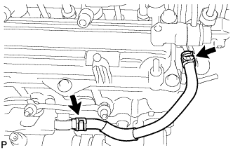
REMOVE FUEL TUBE SUB-ASSEMBLY
-
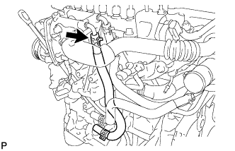
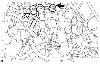
Disconnect the exhaust fuel addition injector connector.
-
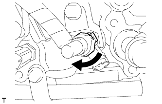
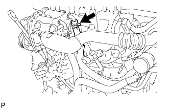
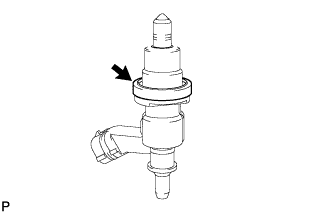
Turn the retainer as shown in the illustration.
-
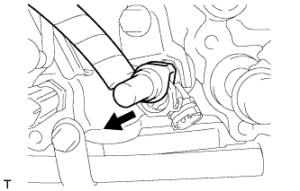
Disconnect the fuel tube from the exhaust fuel addition injector.
-
Remove the check valve and gasket.
Text in Illustration 
Check Valve -
Remove the union bolt, gasket and fuel tube.
-
-
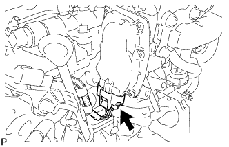
REMOVE EXHAUST FUEL ADDITION INJECTOR ASSEMBLY
-
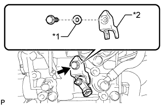
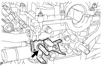
Text in Illustration *1 Washer *2 Nozzle Holder Clamp Remove the bolt, washer, nozzle holder clamp, exhaust fuel addition injector and gasket.
-
-
REMOVE FUEL INJECTOR SEAL
-
Remove the fuel injector seal from the exhaust fuel addition injector.
-
-
REMOVE NO. 3 FUEL HOSE
-
REMOVE SUPPLY PUMP ASSEMBLY
-
Remove the 2 bolts, supply pump and No. 1 supply pump drive coupling.
-
Remove the O-ring from the supply pump.
-
-
REMOVE FUEL HOSE PROTECTOR
-
Remove the fuel hose protector.
-
-
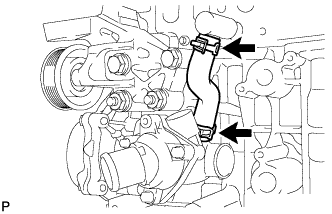
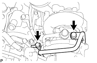
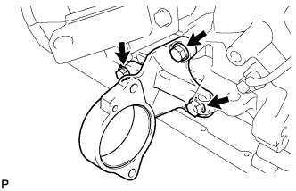
REMOVE NO. 3 WATER BY-PASS PIPE
-
Remove the 2 bolts and No. 3 water by-pass pipe.
-
-
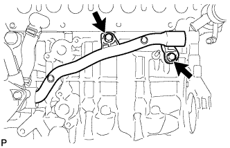
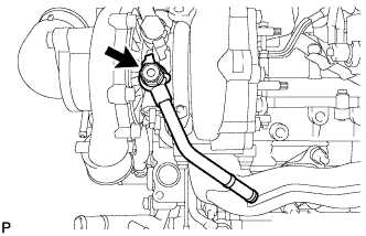
REMOVE NO. 1 TURBO OIL PIPE
-
Remove the 2 union bolts, 2 gaskets and No. 1 turbo oil pipe.
-
-
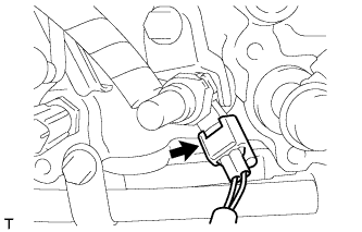
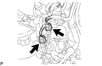
REMOVE NO. 1 VACUUM SWITCHING VALVE ASSEMBLY
-
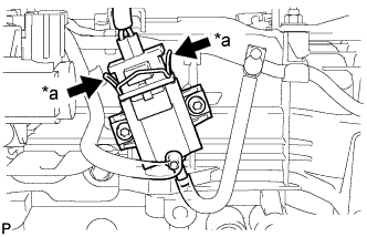
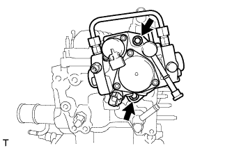
Text in Illustration *a Pinch Pinch the clip as shown in the illustration and pull out the VSV connector.
-
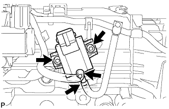
Disconnect the 2 vacuum hoses.
-
Using a 4 mm hexagon socket wrench, remove the 2 bolts and VSV.
-
-
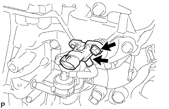
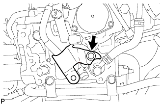
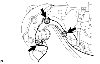
REMOVE VACUUM REGULATING VALVE ASSEMBLY
-
Disconnect the vacuum regulating valve connector.
-
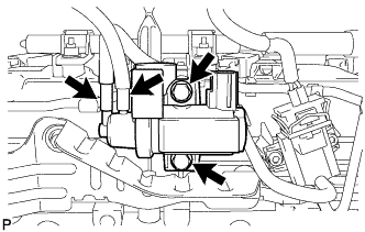
Disconnect the 2 vacuum hoses.
-
Remove the 2 bolts and vacuum regulating valve.
-
-
REMOVE VACUUM TRANSMITTING HOSE ASSEMBLY
-
Detach the 10 clamps and remove the 2 vacuum transmitting hoses.
-
-
REMOVE NO. 1 MANIFOLD CONVERTER INSULATOR
-
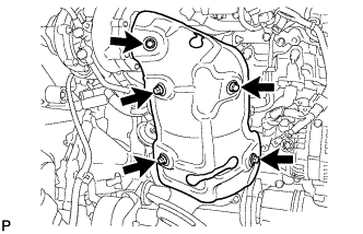
Remove the 5 bolts and No. 1 manifold converter insulator.
-
-
REMOVE MANIFOLD STAY
-
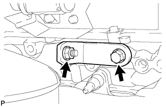
Remove the bolt, nut and manifold stay.
-
-
REMOVE NO. 2 MANIFOLD STAY
-
Remove the 3 bolts and No. 2 manifold stay.
-
-
REMOVE NO. 2 EXHAUST MANIFOLD STAY
-
Remove the 2 bolts, nut and No. 2 exhaust manifold stay.
-
-
REMOVE EXHAUST MANIFOLD CONVERTER SUB-ASSEMBLY
-
Disconnect the 2 connectors.
-
Remove the 3 nuts, exhaust manifold converter and gasket.
-
-
REMOVE NO. 1 TURBO WATER HOSE (for Manual Transaxle)
-
REMOVE NO. 5 WATER BY-PASS HOSE (for Manual Transaxle)
-
REMOVE NO. 2 WATER BY-PASS HOSE (for Automatic Transaxle)
-
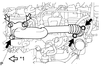
REMOVE EGR COOLER WITH PIPE ASSEMBLY
-
Disconnect the vacuum hose.
-
Text in Illustration *1 Nut Remove the 6 bolts, 2 nuts and EGR cooler with pipe.
-
Remove the gasket from the No. 1 EGR pipe and the gasket from the EGR cooler.
-
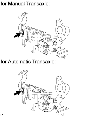
Remove the O-ring from the EGR cooler.
-
-
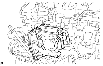
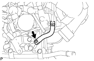
REMOVE TURBO OIL OUTLET PIPE
-
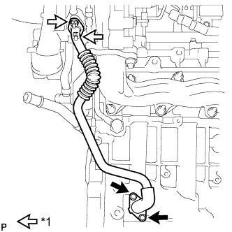
Text in Illustration *1 Nut Remove the 2 nuts, 2 bolts, turbo oil outlet pipe and 2 gaskets.
-
-
REMOVE NO. 1 TURBO INSULATOR
-
Remove the 2 bolts and No. 1 turbo insulator.
-
-
REMOVE NO. 1 TURBO WATER PIPE SUB-ASSEMBLY (for Manual Transaxle)
-
Remove the union bolt, gasket and No. 1 turbo water pipe.
-
-
DISCONNECT NO. 3 WATER BY-PASS HOSE
-
REMOVE NO. 2 TURBO WATER PIPE SUB-ASSEMBLY (for Manual Transaxle)
-
Text in Illustration *1 Union Bolt Remove the union bolt and gasket.
-
Remove the bolt and No. 2 turbo water pipe.
-
-
REMOVE NO. 5 WATER BY-PASS PIPE (for Automatic Transaxle)
-
Remove the 2 bolts and No. 5 water by-pass pipe.
-
-
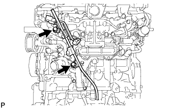
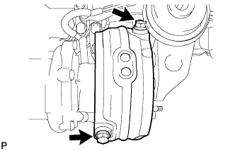
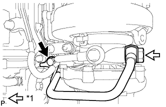
REMOVE NO. 2 TURBO OIL PIPE
-
Disconnect the vacuum hose.
-
Remove the 2 union bolts, 2 gaskets and No. 2 turbo oil pipe.
-
-
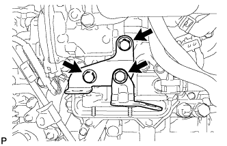
REMOVE TURBOCHARGER STAY
-
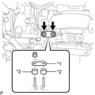
Text in Illustration *1 Turbocharger Stay *2 Collar Remove the 2 nuts, turbocharger stay and 2 collars.
Note
Do not reuse the turbocharger stay.
-
-
REMOVE TURBOCHARGER SUB-ASSEMBLY
-
Disconnect the vacuum hose.
-
Remove the 3 nuts, turbocharger and gasket.
-
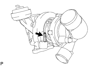
Using an E8 "TORX" wrench, remove the stud bolt.
-
-
REMOVE EXHAUST MANIFOLD
-
Remove the 8 nuts, 8 collars, exhaust manifold and gasket.
-
-
REMOVE DRIVE SHAFT BEARING BRACKET
-
Remove the 3 bolts and bearing bracket.
-