CYLINDER HEAD GASKET INSTALLATION

-
SELECT CYLINDER HEAD GASKET
-
Check the piston protrusions for each cylinder.
-
Clean the cylinder block sub-assembly with solvent.
-
Set the piston of the cylinder to be measured to slightly before TDC.
-
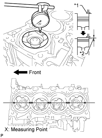
Text in Illustration *1 Measuring Tip *2 Protrusion Place a dial indicator on the cylinder block sub-assembly, and set the measuring tip as shown in the illustration.
-
Set the dial indicator at 0 mm (0 in.).
Tech Tips
Make sure that the measuring tip is perpendicular to the cylinder block gasket surface and piston head when taking the measurements.
-
Find where the piston head protrudes most by slowly turning the crankshaft clockwise and counterclockwise.
-
Measure each cylinder at 2 places as shown in the illustration, making a total of 8 measurements.
-
For the piston protrusion value of each cylinder, use the average of the 2 measurements of each cylinder.
Standard piston protrusion 0.300 to 0.560 mm (0.0118 to 0.0220 in.) If the protrusion is not as specified, remove the piston and connecting rod and reinstall it.
-
-
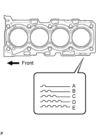
Select a new cylinder head gasket.
New Installed Cylinder Head Gasket Thickness Cutout Mark Specified Condition A 1.00 to 1.10 mm (0.0394 to 0.0433 in.) B 1.05 to 1.15 mm (0.0413 to 0.0453 in.) C 1.10 to 1.20 mm (0.0433 to 0.0472 in.) D 1.15 to 1.25 mm (0.0453 to 0.0492 in.) E 1.20 to 1.30 mm (0.0472 to 0.0512 in.) Tech Tips
Cylinder head gaskets are marked A, B, C, D or E accordingly.
-
Select the largest piston protrusion value from the measurements and then select a new appropriate gasket according to the table below.
Gasket Size Item Specified Condition Piston protrusion 0.300 to 0.355 mm (0.0118 to 0.0140 in.) 0.355 to 0.405 mm (0.0140 to 0.0159 in.) 0.405 to 0.455 mm (0.0159 to 0.0179 in.) 0.455 to 0.505 mm (0.0179 to 0.0199 in.) 0.505 to 0.560 mm (0.0199 to 0.0220 in.) Gasket to be used A B C D E
-
-
-
INSTALL CYLINDER HEAD GASKET
-
INSTALL CYLINDER HEAD SUB-ASSEMBLY
-
Using the crankshaft pulley bolt, set the No. 1 cylinder to 90° BTDC/compression.
-
Place the cylinder head gasket in position on the cylinder block sub-assembly.
-
Place the cylinder head sub-assembly on the cylinder head gasket.
Note
Be careful of the installation direction.
-
Apply a light coat of engine oil to the threads and under the heads of the cylinder head bolts.
-
Temporarily install the cylinder head bolts.
Tech Tips
If any bolt is broken or deformed, replace it.
-
Step 1:
Tech Tips
For new bolts, perform steps 1 to 3. For used bolts, perform only step 1.
-
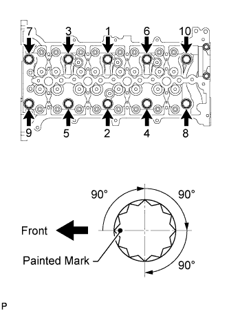
Uniformly tighten the 10 cylinder head bolts in several steps in the sequence shown in the illustration.
- Torque:
- 50 N*m { 510 kgf*cm, 37 ft.*lbf }
Tech Tips
If any one of the cylinder head bolts does not meet the torque specification, replace the cylinder head bolt.
-
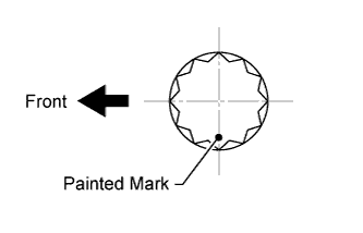
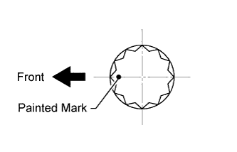
Mark the front of the cylinder head bolts with paint.
-
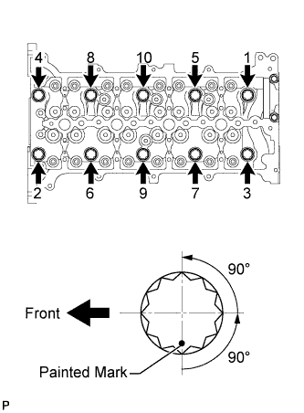
Tighten the cylinder head bolts by 90° in the sequence shown in the illustration.
-
Perform the step above twice.
-
Check that the painted marks are positioned as shown in the illustration.
-
-
Step 2:
-
Loosen the cylinder head bolts by 90° in the sequence shown in the illustration.
-
Perform the step above again.
-
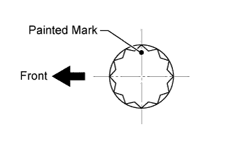
Check that the painted marks are positioned as shown in the illustration.
-
-
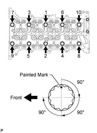
Step 3:
-
Retighten the cylinder head bolts by 90° in the sequence shown in the illustration.
-
Perform the above step twice.
-
Check that the painted marks are positioned as shown in the illustration.
-
-
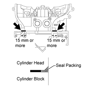
Apply seal packing between the cylinder head sub-assembly and cylinder block sub-assembly in the areas shown in the illustration.
Seal packing Toyota Genuine Seal Packing Black, Three Bond 1207B or equivalent Standard seal packing application length 15 mm (0.591 in.) or more Note
-
Before applying seal packing, clean the cylinder head sub-assembly and cylinder block sub-assembly surfaces near the cylinder head gasket. Be sure to remove any oil that has seeped in between the cylinder head gasket and cylinder head sub-assembly or cylinder block sub-assembly.
-
When the contact surfaces are wet, wipe them off with an oil-free cloth before applying seal packing.
-
Wipe off any seal packing that seeps out from the groove in the cylinder head sub-assembly.
-
Do not start the engine for at least 4 hours after installation.
-
-
-
INSTALL GLOW PLUG ASSEMBLY
-
Using a 10 mm deep socket wrench, install the 4 glow plug sub-assemblies.
- Torque:
- 12 N*m { 125 kgf*cm, 9 ft.*lbf }
-
Install the No. 1 glow plug connector with the 4 nuts.
- Torque:
- 2.2 N*m { 22 kgf*cm, 19 in.*lbf }
-
Install the 4 glow plug screw grommets.
-
-
INSTALL FUEL INJECTOR SEAL
-
Install a new fuel injector seal to the exhaust fuel addition injector assembly.
-
-
INSTALL EXHAUST FUEL ADDITION INJECTOR ASSEMBLY
Note
If there is foreign matter on the installation surface of the exhaust fuel addition injector assembly, be sure to clean the injector before installation.
-
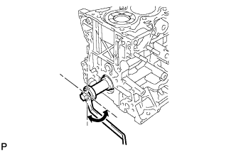
Install a new gasket, the exhaust fuel addition injector assembly, the nozzle holder clamp, and the washer with the bolt.
- Torque:
- 29 N*m { 296 kgf*cm, 21 ft.*lbf }
Tech Tips
Align the nozzle holder clamp with the cutouts of the injector as shown in the illustration.
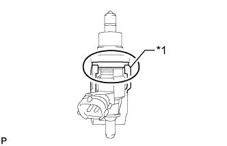
Text in Illustration *1 Nozzle Holder Clamp
-
-
INSTALL CAMSHAFT
-
INSTALL EXHAUST MANIFOLD WITH TURBOCHARGER
-
CONNECT CABLE TO NEGATIVE BATTERY TERMINAL
Note
When disconnecting the cable, some systems need to be initialized after the cable is reconnected Click here.