CYLINDER HEAD REASSEMBLY

-
INSTALL NO. 1 WATER BY-PASS PIPE
Tech Tips
When using a new cylinder head, a No. 1 water by-pass pipe must be installed.
-
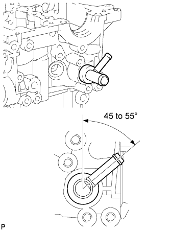
Apply adhesive to a new No. 1 water by-pass pipe.
Adhesive Toyota Genuine Adhesive 1324, Three Bond 1324 or equivalent -
Install the No. 1 water by-pass pipe as shown in the illustration.
-
-
INSTALL WATER OUTLET
Tech Tips
When using a new cylinder head, a water outlet must be installed.
-
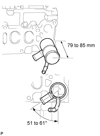
Apply adhesive to a new water outlet.
Adhesive Toyota Genuine Adhesive 1324, Three Bond 1324 or equivalent -
Install the water outlet.
Standard protrusion 79 to 85 mm (3.11 to 3.35 in.) Standard angle 51 to 61°
-
-
INSTALL ELBOW
Tech Tips
When using a new cylinder head, an elbow must be installed.
-
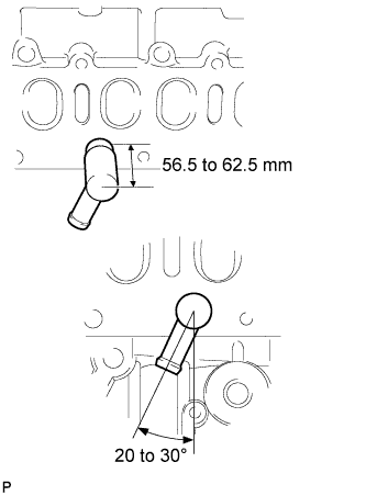
Apply adhesive to a new elbow.
Adhesive Toyota Genuine Adhesive 1324, Three Bond 1324 or equivalent -
Install the elbow.
Standard protrusion 56.5 to 62.5 mm (2.22 to 2.46 in.) Standard angle 20 to 30°
-
-
INSTALL VALVE SPRING SEAT PLATE WASHER
-
Install the valve spring seat washer to the cylinder head.
-
-
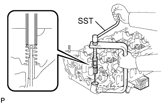
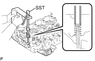
INSTALL VALVE STEM OIL SEAL
-
Apply a light coat of engine oil to a new valve stem oil seal.
-
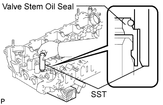
Using SST, push in the valve stem oil seal.
- SST
- 09201-41020
Note
Failure to use SST will cause the seal to be damaged or improperly seated.
-
-
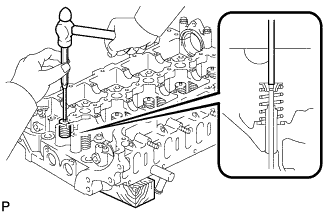
INSTALL INTAKE VALVE
-
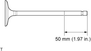
Apply plenty of engine oil to the tip area of the intake valve shown in the illustration.
-
Place the cylinder head on a wooden block.
-
Install the intake valve, inner compression spring and valve spring retainer to the cylinder head.
Note
Install the same parts in the same combination to their original locations.
-
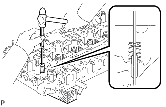
Using SST, compress the inner compression spring and place the valve spring retainer lock around the valve stem.
- SST
- 09202-70020
-
Using a 5 mm pin punch and plastic-faced hammer, lightly tap the valve stem tip to ensure a proper fit.
Note
Be careful not to damage the valve stem tip.
-
-
INSTALL EXHAUST VALVE
-
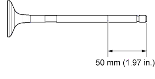
Apply plenty of engine oil to the tip area of the exhaust valve shown in the illustration.
-
Place the cylinder head on a wooden block.
-
Install the exhaust valve, inner compression spring and valve spring retainer to the cylinder head.
Note
Install the same parts in the same combination to their original locations.
-
Using SST, compress the inner compression spring and place the valve spring retainer lock around the valve stem.
- SST
- 09202-70020
-
Using a 5 mm pin punch and plastic-faced hammer, lightly tap the valve stem tip to ensure a proper fit.
Note
Be careful not to damage the valve stem tip.
-