AIR FUEL RATIO SENSOR (for Sensor 1) INSTALLATION

-
INSTALL AIR FUEL RATIO SENSOR
-
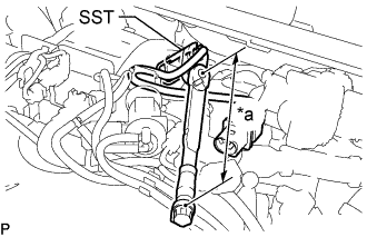
Text in Illustration *a Fulcrum Length Using SST, install the air fuel ratio sensor.
- SST
- 09224-00010
- Torque:
- without SST
- 50 N*m { 510 kgf*cm, 37 ft.*lbf }
- with SST
- 45 N*m { 463 kgf*cm, 33 ft.*lbf }
Note
If an air fuel ratio sensor has been struck or dropped, replace it.
Tech Tips
-
Use a torque wrench with a fulcrum length of 300 mm (11.8 in.). When using a torque wrench with a fulcrum length that is not 300 mm (11.8 in.), calculate the torque specification for the torque wrench and SST based on the "without SST" torque specification.
-
Make sure SST and the wrench are connected in a straight line.
-
Perform "Inspection After Repairs" after replacing the air fuel ratio sensor Click here.
-
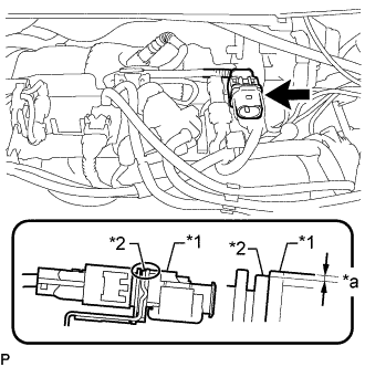
Text in Illustration *1 Air Fuel Ratio Sensor Connector *2 Bracket *a 1.5 mm (0.0591 in.) or less Lower the air fuel ratio sensor connector to the position shown in the illustration and connect the air fuel ratio sensor connector.
-
Attach the clamp.
-
-
CONNECT SENSOR INSULATOR
-
Connect the sensor insulator with the nut.
- Torque:
- 8.0 N*m { 82 kgf*cm, 71 in.*lbf }
-
-
INSPECT FOR EXHAUST GAS LEAK
If gas is leaking, tighten the areas necessary to stop the leak. Replace damaged parts as necessary.
-
INSTALL NO. 1 ENGINE COVER
-
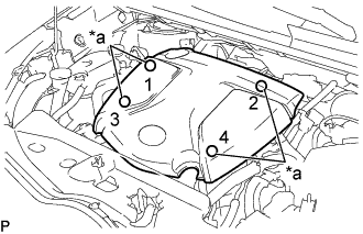
Text in Illustration *a Installation Points Attach the 4 clips to install the No. 1 engine cover.
Tech Tips
When attaching the clips, press the protrusions on the top of the No. 1 engine cover at the clip installation points.
-
-
PERFORM AIR FUEL RATIO SENSOR INITIALIZATION