AUDIO AND VISUAL SYSTEM (for Radio Receiver Type) Speaker Circuit
DESCRIPTION
The radio receiver assembly sends sound signals to the speakers.
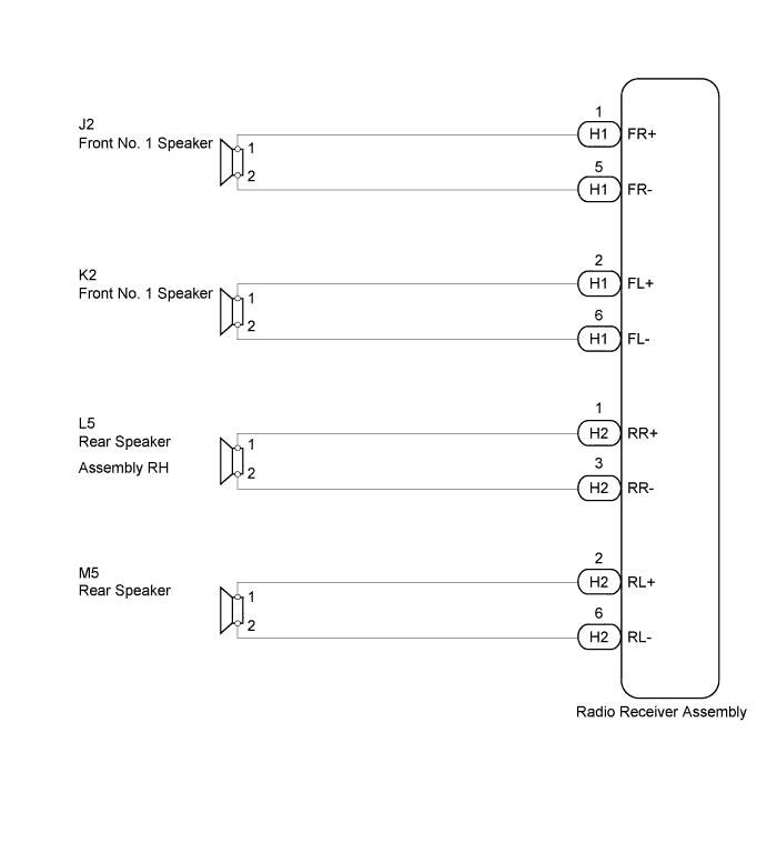
WIRING DIAGRAM
INSPECTION PROCEDURE
PROCEDURE
-
CHECK SPEAKER
-
Check the malfunctioning speakers.
Result Result Proceed to Malfunction in front speaker area A Malfunction in rear speaker area B
B 
INSPECT REAR SPEAKER ASSEMBLY Click here
A 
-
-
INSPECT FRONT NO. 1 SPEAKER ASSEMBLY
-
Remove the front No. 1 speaker assembly Click here.
-
Inspect the front No. 1 speaker assembly Click here.
NG 
REPLACE FRONT NO. 1 SPEAKER ASSEMBLY Click here
OK
-
-
CHECK HARNESS AND CONNECTOR (RADIO RECEIVER - FRONT NO. 1 SPEAKER)
-
Disconnect the H11 radio receiver assembly connector.
-
Disconnect the J2*1 and/or K2*2 front No. 1 speaker assembly connector.
-
*1: for RH Side
-
*2: for LH Side
-
-
Measure the resistance according to the value(s) in the table below.
Standard Resistance for RH Side Tester Connection Condition Specified Condition H1-1 (FR+) - J2-1 Always Below 1 Ω H1-5 (FR-) - J2-2 H1-1 (FR+) - Body ground Always 10 kΩ or higher H1-5 (FR-) - Body ground for LH Side Tester Connection Condition Specified Condition H1-2 (FL+) - K2-1 Always Below 1 Ω H1-6 (FL-) - K2-2 H1-2 (FL+) - Body ground Always 10 kΩ or higher H1-6 (FL-) - Body ground
NG
REPAIR OR REPLACE HARNESS OR CONNECTOR
OK 
REPLACE RADIO RECEIVER ASSEMBLY Click here
-
-
INSPECT REAR SPEAKER ASSEMBLY
-
Remove the rear speaker assembly Click here.
-
Inspect the rear speaker assembly Click here.
NG
REPLACE REAR SPEAKER ASSEMBLY Click here
OK
-
-
CHECK HARNESS AND CONNECTOR (RADIO RECEIVER - REAR SPEAKER)
-
Disconnect the H2 radio receiver assembly connector.
-
Disconnect the L5*1 and/or M5*2 rear speaker assembly connector.
-
*1: for RH Side
-
*2: for LH Side
-
-
Measure the resistance according to the value(s) in the table below.
Standard Resistance for RH Side Tester Connection Condition Specified Condition H2-1 (RR+) - L5-1 Always Below 1 Ω H2-3 (RR-) - L5-2 H2-1 (RR+) - Body ground Always 10 kΩ or higher H2-3 (RR-) - Body ground for LH Side Tester Connection Condition Specified Condition H2-2 (RL+) - M5-1 Always Below 1 Ω H2-6 (RL-) - M5-2 H2-2 (RL+) - Body ground Always 10 kΩ or higher H2-6 (RL-) - Body ground
NG
REPAIR OR REPLACE HARNESS OR CONNECTOR
OK
REPLACE RADIO RECEIVER ASSEMBLY Click here
-