STEERING COLUMN ASSEMBLY REASSEMBLY

Note
When using a vise, do not overtighten it.
-
INSTALL STEERING LOCK ACTUATOR ASSEMBLY (w/ Entry and Start System)
-
Secure the steering column assembly in a vise.
-
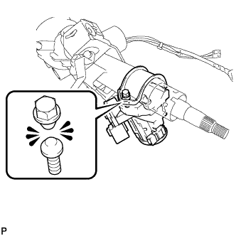
Temporarily install the steering lock actuator assembly with a new tapered-head bolt.
Note
Be sure to use a new tapered-head bolt.
-
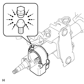
Tighten the tapered-head bolt until the bolt head breaks off.
-
-
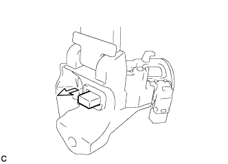
INSTALL UNLOCK WARNING SWITCH ASSEMBLY (w/o Entry and Start System)
-
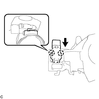
Attach the 2 claws to install the unlock warning switch assembly to the steering column upper bracket.
Tech Tips
Slide the unlock warning switch assembly in the direction indicate by the arrow in the illustration to install it.
-
-
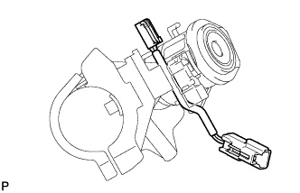
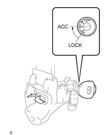
INSTALL IGNITION SWITCH LOCK CYLINDER ASSEMBLY (w/o Entry and Start System)
-
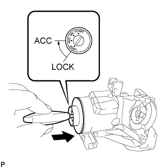
Make sure that the ignition switch lock cylinder assembly is in the ACC position.
-
Install the ignition switch lock cylinder assembly to the steering column upper bracket.
-
Make sure that the ignition switch lock cylinder assembly is securely installed.
-
-
INSTALL TRANSPONDER KEY AMPLIFIER (w/o Entry and Start System)
-
Align the transponder key amplifier with the steering column upper bracket. Tilt the amplifier slightly and slide it into position.
-
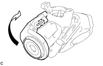
Push the transponder key amplifier to install it to the steering column upper bracket by engaging the 2 claws.
-
-
INSTALL IGNITION OR STARTER SWITCH ASSEMBLY (w/o Entry and Start System)
-
except Manual transaxle:
Install the key interlock solenoid.
-
Install the solenoid wire to the steering column upper bracket.
-
Connect the solenoid wire connector to the key interlock solenoid.
-
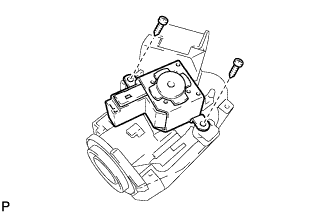
Install the key interlock solenoid to the steering column upper bracket with the 2 screws.
- Torque:
- 1.5 N*m { 15 kgf*cm, 13 in.*lbf }
-
-
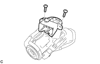
Install the ignition or starter switch assembly to the steering column upper bracket with the 2 screws.
- Torque:
- 1.5 N*m { 15 kgf*cm, 13 in.*lbf }
-
except Manual transaxle:
Connect the solenoid wire connector to the ignition or starter switch assembly.
-
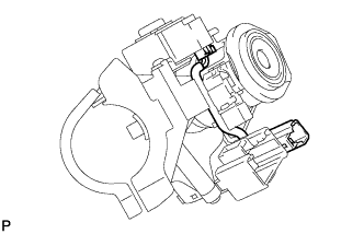
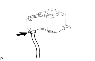
except Manual transaxle:
Make sure that the solenoid wire runs securely through the gap of the steering column upper bracket as shown in the illustration.
-
-
INSPECT STEERING LOCK OPERATION (w/o Entry and Start System)
-
Check that the steering lock mechanism is activated when the key is removed.
-
Check that the steering lock mechanism is deactivated when the key is inserted and turned to the ACC position.
Tech Tips
If there is any abnormality, replace the ignition switch lock cylinder assembly or steering column upper bracket assembly.
-
-
INSTALL STEERING COLUMN UPPER WITH SWITCH BRACKET ASSEMBLY (w/o Entry and Start System)
-
Secure the steering column assembly in a vise.
-
Temporarily install the steering column upper with switch bracket assembly to the steering column assembly with a new tapered-head bolt.
Note
Be sure to use a new tapered-head bolt.
-
Tighten the tapered-head bolt until the bolt heads breaks off.
-
-
INSTALL POWER STEERING ECU ASSEMBLY
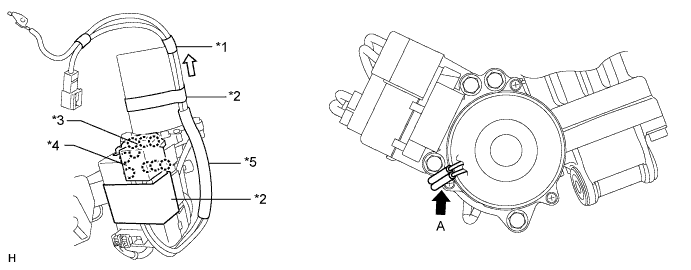
Text in Illustration *1 Marking Tape *2 Heat Resistant Tape *3 Bus Bar Cover *4 Power Terminal Cover *5 Protective Tube - -
-
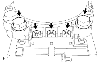
Temporarily install the power steering ECU with 3 new screws and 2 new bolts.
-
Tighten the 3 screws.
- Torque:
- 3.2 N*m { 33 kgf*cm, 28 in.*lbf }
-
Tighten the 2 bolts.
- Torque:
- 20 N*m { 204 kgf*cm, 15 ft.*lbf }
-
Connect the 2 wire harnesses with 2 new terminal screws.
- Torque:
- 3.2 N*m { 33 kgf*cm, 28 in.*lbf }
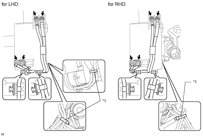
Text in Illustration *1 Band - - -
for LHD:
Install 2 new bands.
for RHD:
Install a new band.
Note
Do not allow the wire harness to hang along the side of the power steering ECU.
-
Connect the 2 connectors.
-
Install 2 new clamps.
-
Install 2 new terminal covers.
-
For bus bar cover:
Attach the 3 claws to install the cover.
-
For power terminal cover:
Attach the 6 claws to install the cover.
-
-
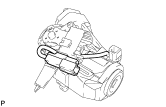
Place new heat resistant tape as shown in the illustration.
-
Align the wire harness with the part of the motor housing labeled A and pull the wire harness in the direction indicated by the white arrow in the illustration.
Note
Make sure the marking tape is positioned at the end of the motor as shown in the illustration.
-
Wrap tape around the wire harness and motor 2 times or more at a location between the tape marking the edge of the motor and the protective tube to secure the wire harness to the motor.
Tech Tips
The marking tape is already wrapped around the wire harness and does not need to be replaced.
-
Wrap tape around the wire harness and ECU as shown in the illustration.
-
-