STEERING COLUMN ASSEMBLY DISASSEMBLY

Note
When using a vise, do not overtighten it.
-
REMOVE POWER STEERING ECU ASSEMBLY
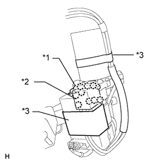
Text in Illustration *1 Bas Bar Cover *2 Power Terminal Cover
-
Remove the 2 terminal covers.
-
For bus bar cover:
Detach the 3 claws and remove the cover.
-
For power terminal cover:
Detach the 6 claws and remove the cover.
-
-
Remove the 2 pieces of tape.
-
Remove the 2 terminal screws.
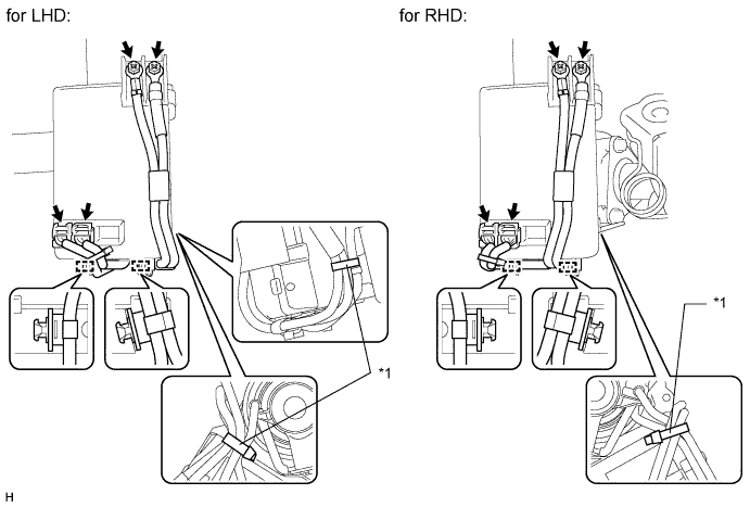
Text in Illustration *1 Band - - -
Disconnect the 2 connectors.
-
Remove the 2 clamps.
-
for LHD:
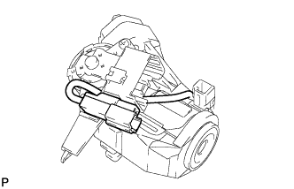
Cut off the 2 bands.
for RHD:
Cut off the band.
-
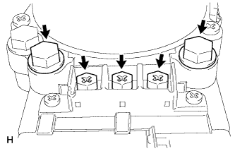
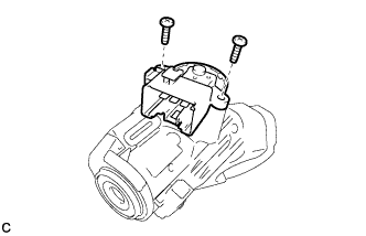
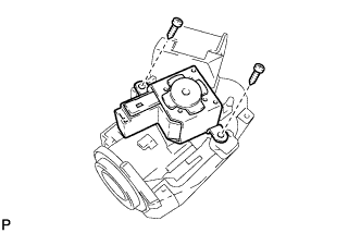
Text in Illustration *3 Heat Resistant Tape Remove the 3 screws and 2 bolts.
Note
Be sure not to remove any other bolts or screws other than those indicated in the illustration.
-
Remove the power steering ECU from the steering column assembly.
-
-
REMOVE STEERING LOCK ACTUATOR ASSEMBLY (w/ Entry and Start System)
-
Secure the steering column assembly in a vise.
-
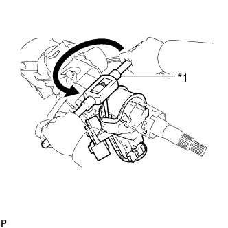
Using a center punch, mark the center of the tapered-head bolt.
-
Using a 3 to 4 mm (0.118 to 0.157 in.) diameter drill bit, drill a hole in the tapered-head bolt.
-
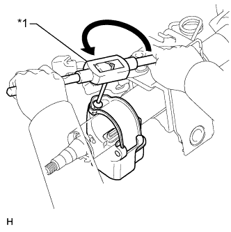
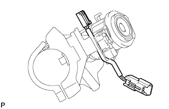
Text in Illustration *1 Screw Extractor Using a screw extractor, remove the tapered-head bolt, and then remove the steering lock actuator assembly from the steering column assembly.
-
-
REMOVE STEERING COLUMN UPPER WITH SWITCH BRACKET ASSEMBLY (w/o Entry and Start System)
-
Secure the steering column assembly in a vise.
-
Using a center punch, mark the center of the tapered-head bolt.
-
Using a 3 to 4 mm (0.118 to 0.157 in.) diameter drill bit, drill a hole in the tapered-head bolt.
-
Text in Illustration *1 Screw Extractor Using a screw extractor, remove the tapered-head bolt, and then remove the steering column upper with switch bracket assembly from the steering column assembly.
-
-
REMOVE IGNITION OR STARTER SWITCH ASSEMBLY (w/o Entry and Start System)
-
except Manual transaxle:
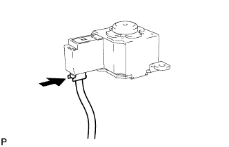
Disconnect the solenoid wire connector from the ignition or starter switch assembly.
-
Remove the 2 screws and ignition or starter switch assembly from the steering column upper bracket.
-
except Manual transaxle:
Remove the key interlock solenoid.
-
Remove the 2 screws and key interlock solenoid from the steering column upper bracket.
-
Disconnect the solenoid wire connector from the key interlock solenoid.
-
Remove the solenoid wire from the steering column upper bracket.
-
-
-
REMOVE TRANSPONDER KEY AMPLIFIER (w/o Entry and Start System)
-
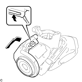
Using a screwdriver, widen the 2 claws hanging onto the upper bracket by approximately 1.0 mm (0.0394 in.).
-
Remove the transponder key amplifier with the claw open.
Note
Using excessive force may damage the amplifier.
-
-
REMOVE IGNITION SWITCH LOCK CYLINDER ASSEMBLY (w/o Entry and Start System)
-
Turn the ignition switch lock cylinder assembly to the ACC position.
-
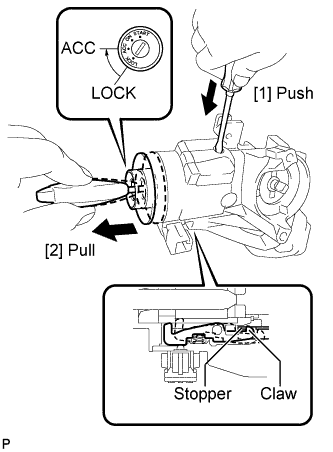
Insert a screwdriver into the hole of the steering column upper bracket as shown in the illustration. Pull the ignition switch lock cylinder assembly until its claw contacts the stopper of the steering column upper bracket.
Note
Make sure to pull the ignition switch lock cylinder assembly until its claw contacts the stopper of the steering column upper bracket. Failure to do so will affect later steps.
-
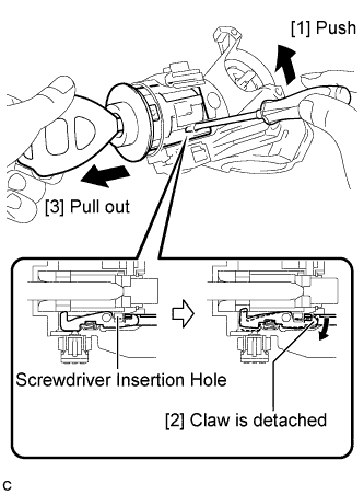
Insert a screwdriver into the hole of the steering column upper bracket. Push the screwdriver upward as shown in the illustration to detach the claw of the ignition switch lock cylinder assembly, and pull out the ignition switch lock cylinder assembly to remove it.
-
-
REMOVE UNLOCK WARNING SWITCH ASSEMBLY (w/o Entry and Start System)
-
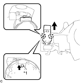
Text in Illustration *1 Center Part Remove the unlock warning switch assembly by pushing up the center part and releasing the 2 claws.
Tech Tips
Slide the unlock warning switch in the direction indicated by the arrow in the illustration to remove it.
-