Some of these service operations affect the SRS. Read the precautionary notices concerning the SRS before servicing the steering column (Click here).
-
Use the same procedure for RHD and LHD vehicles.
-
The procedure listed below is for LHD vehicles.
- Click here
PLACE FRONT WHEELS FACING STRAIGHT AHEAD
- Click here
DISCONNECT CABLE FROM NEGATIVE BATTERY TERMINAL
CAUTION:Wait at least 90 seconds after disconnecting the cable from the negative (-) battery terminal to disable the SRS system.
Note:
-
w/ Navigation System for HDD:
After the ignition switch is turned off, the HDD navigation system requires approximately a minute to record various types of memory and settings. As a result, after turning the ignition switch off, wait a minute or more before disconnecting the cable from the negative (-) battery terminal.
-
When disconnecting the cable, some systems need to be initialized after the cable is reconnected (Click here).
-
- Click here
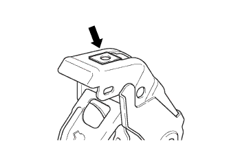
REMOVE STEERING PAD
-
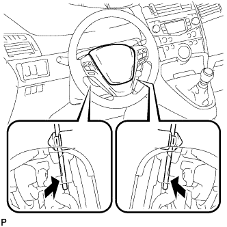
Using a screwdriver, detach the 2 springs.
-
Pull out the steering pad from the steering wheel as shown in the illustration and support the steering pad with one hand.
Note:When removing the steering pad, do not pull the airbag wire harness.
-
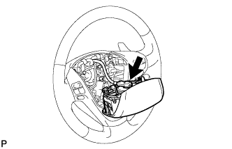
Disconnect the horn connector.
-
Disconnect the connector and remove the steering pad.
Note:When handling the airbag connector, take care not to damage the airbag wire harness.
-
- Click here
REMOVE STEERING WHEEL ASSEMBLY
-
Fully extend and tilt up the steering wheel.
-
Remove the steering wheel assembly (Click here).
-
- Click here
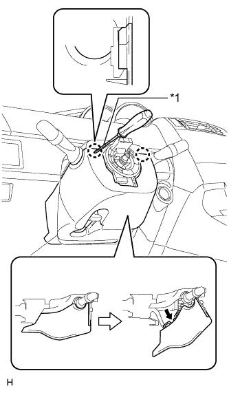
REMOVE LOWER STEERING COLUMN COVER
Note:Removing the steering column cover in an incorrect order will cause the steering column cover to break.
-
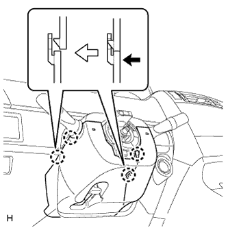
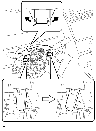
Push the right and left sides of the lower steering column cover and detach the 4 claws.
-
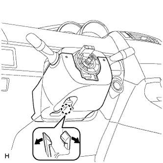
Insert fingers into the opening of the tilt lever of the lower steering column cover to detach the claw.
Tip:Spread the claw to detach it.
-
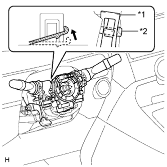
Using a screwdriver, disengage the 2 claws.
Table 1. Text in Illustration *1 Protective Tape -
Turn the steering column lower cover and remove the lower steering column cover as shown in the illustration.
-
- Click here
REMOVE UPPER STEERING COLUMN COVER
-
Detach the claw and 2 pins, and remove the upper steering column cover.
-
- Click here
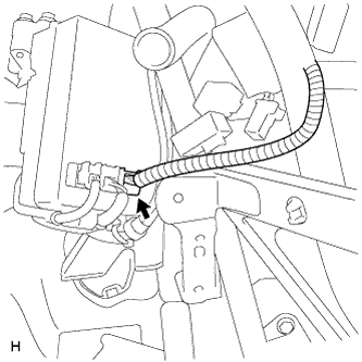
REMOVE COMBINATION SWITCH ASSEMBLY WITH SPIRAL CABLE SUB-ASSEMBLY
-
Disconnect the connectors from the combination switch assembly with spiral cable sub-assembly.
-
Use pliers to hold the clamp and raise the claw with a screwdriver. Remove the combination switch assembly with spiral cable sub-assembly from the steering column assembly.
Table 2. Text in Illustration *1 Clamp *2 Claw
-
- Click here
REMOVE COLUMN HOLE COVER SILENCER SHEET
-
Fold back the floor carpet, and then remove the 2 clips and then column hole cover silencer sheet.
-
- Click here
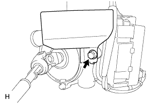
DISCONNECT NO. 2 STEERING INTERMEDIATE SHAFT ASSEMBLY
-
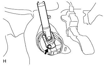
Remove the bolt.
Note:Do not disconnect the No. 2 steering intermediate shaft assembly from the steering intermediate shaft.
-
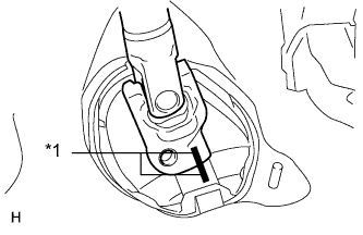
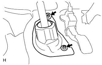
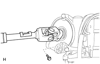
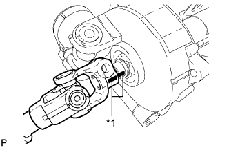
Put matchmarks on the No. 2 steering intermediate shaft assembly and steering intermediate shaft.
Table 3. Text in Illustration *1 Matchmark -
Disconnect the No. 2 steering intermediate shaft assembly from the steering intermediate shaft.
-
- Click here
REMOVE INSTRUMENT PANEL SAFETY PAD SUB-ASSEMBLY
-
Remove the instrument panel safety pad sub-assembly (Click here).
-
- Click here
REMOVE LOWER NO. 1 INSTRUMENT PANEL AIRBAG ASSEMBLY
-
Remove the lower No. 1 instrument panel airbag assembly (Click here).
-
- Click here
REMOVE BRAKE PEDAL SUPPORT SUB-ASSEMBLY
-
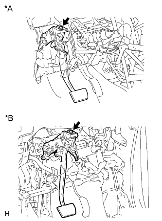
Remove the bolt and separate the brake pedal support sub-assembly from the instrument panel reinforcement.
Table 4. Text in Illustration *A for LHD *B for RHD -
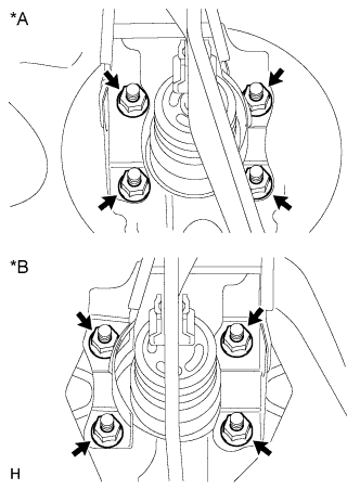
Remove the 4 nuts and brake pedal support sub-assembly.
Table 5. Text in Illustration *A for LHD *B for RHD -
Remove the nut from the brake pedal support sub-assembly.
-
- Click here
REMOVE STEERING COLUMN ASSEMBLY
-
Disconnect the power steering ECU connector.
-
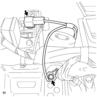
Disconnect the connector and detach the connector clamp.
-
Remove the bolt.
-
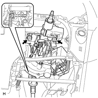
Remove the bolt, 2 nuts and steering column assembly.
Note:
-
Do not release the tilt lever when the steering column assembly is not installed on the vehicle.
-
Do not drop or strike the steering column assembly. If dropped or struck, replace it with a new one.
-
-
- Click here
REMOVE STEERING COLUMN PROTECTOR (for Manual Transaxle RHD)
-
Remove the bolt and steering column protector from the steering column assembly.
-
- Click here
REMOVE NO. 2 STEERING INTERMEDIATE SHAFT ASSEMBLY
-
Remove the bolt.
Note:Do not remove the No. 2 steering intermediate shaft assembly from the steering column assembly.
-
Put matchmarks on the No. 2 steering intermediate shaft assembly and steering column assembly.
Table 6. Text in Illustration *1 Matchmark -
Remove the No. 2 steering intermediate shaft assembly from the steering column assembly.
-