PARKING BRAKE ASSEMBLY REASSEMBLY

Tech Tips
-
Use the same procedure for the RH and LH sides.
-
The procedure listed below is for the LH side.
-
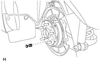
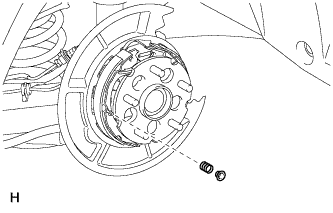
INSTALL NO. 1 PARKING BRAKE SHOE HOLD DOWN SPRING PIN
-
Install the No. 1 parking brake shoe hold down spring pin.
-
-
INSTALL NO. 2 PARKING BRAKE SHOE HOLD DOWN SPRING PIN
-
Install the No. 2 parking brake shoe hold down spring pin.
-
-
APPLY HIGH TEMPERATURE GREASE
-
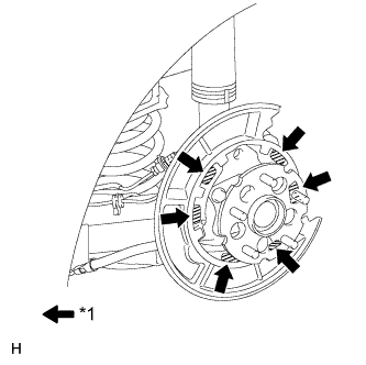
Text in Illustration *1 High temperature grease Apply high temperature grease to the areas of the backing plate that contact the shoe.
-
-
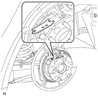
CONNECT NO. 3 PARKING BRAKE CABLE ASSEMBLY
-
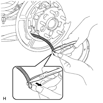
Using needle-nose pliers, connect the No. 3 parking brake cable assembly to the parking brake shoe lever as shown in the illustration.
Note
Be careful not to damage the No. 3 parking brake cable assembly.
-
-
INSTALL NO. 2 PARKING BRAKE SHOE ASSEMBLY
-
Install the No. 2 parking brake shoe, shoe hold down spring and shoe hold down spring cup.
-
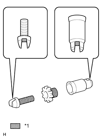
Text in Illustration *1 High temperature grease Apply high temperature grease to the threads and all contact surfaces of the parking brake shoe adjuster screw set.
-
Set the No. 2 parking brake shoe and shoe adjuster screw set in place.
-

Connect the tension spring.
-
-
INSTALL PARKING BRAKE SHOE STRUT
-
Install the parking brake shoe strut.
-
-
INSTALL NO. 1 PARKING BRAKE SHOE ASSEMBLY LH
-
Install the No. 1 parking brake shoe, shoe hold down spring and shoe hold down spring cup.
-
Install the tension spring to the No. 1 parking brake shoe.
-
-
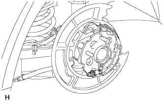
INSTALL PARKING BRAKE SHOE RETURN SPRING
-
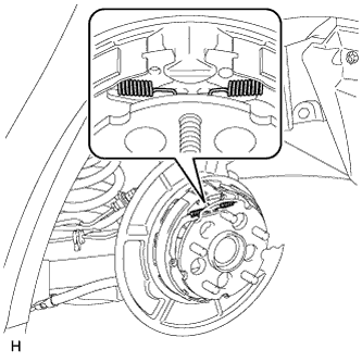
Install the 2 return springs.
Tech Tips
First install the front side spring and then the rear side spring.
-
-
CHECK PARKING BRAKE INSTALLATION
-
Check that each part is installed properly.
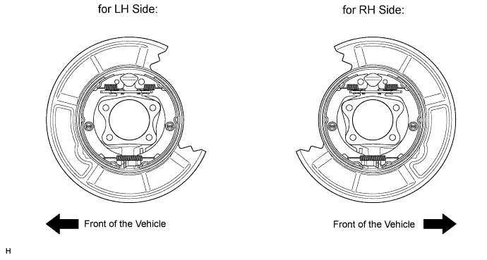
Note
There should be no oil or grease on the friction surfaces of the shoe lining and disc.
-
-
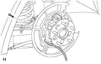
INSTALL REAR DISC
-
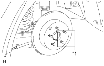
Text in Illustration *1 Matchmark Align the matchmarks and install the rear disc.
-
Install the shoe adjusting hole plug.
-
-
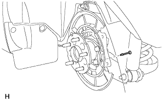
CONNECT REAR DISC BRAKE CYLINDER ASSEMBLY LH
-
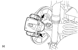
Connect the rear disc brake cylinder with the 2 bolts.
- Torque:
- 57 N*m { 585 kgf*cm, 42 ft.*lbf }
Note
-
Do not twist the brake hose.
-
Make sure that the bolts are free from damage and foreign matter.
-
-
CHECK PARKING BRAKE LEVER TRAVEL
-
Pull the parking brake lever to fully engage the parking brake.
-
Release the lever to disengage the parking brake.
-
Slowly pull the parking brake lever all the way, and count the number of clicks.
Standard parking brake lever travel when pulled with a force of 200 N (20 kgf, 45 lbf) 6 to 9 clicks
-
-
ADJUST PARKING BRAKE LEVER TRAVEL
-
Remove the console box assembly Click here.
-
Completely release the parking brake lever.
-
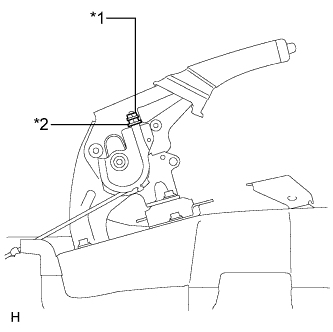
Text in Illustration *1 Lock Nut *2 Adjusting Nut Loosen the lock nut and adjusting nut to completely release the parking brake cable.
-
Temporarily install the hub nuts.
-
Remove the shoe adjusting hole plug.
-
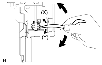
Insert an adjustment tool into the adjustment hole of the disc. Rotate the adjustment wheel in the "X" direction until the shoes are locked. Then rotate the adjustment wheel in the "Y" direction 8 notches.
-
Check that the disc can be rotated lightly. If not, rotate the adjustment wheel in the "Y" direction and check again.
-
Install the hole plug.
-
Remove the hub nuts.
-
Turn the adjusting nut until the parking brake lever travel becomes correct.
Standard parking brake lever travel when pulled with a force of 200 N (20 kgf, 45 lbf) 6 to 9 clicks -
Using a wrench or equivalent, hold the adjusting nut and tighten the lock nut.
- Torque:
- 6.0 N*m { 61 kgf*cm, 53 in.*lbf }
-
Operate the parking brake lever 3 to 4 times, and check the parking brake lever travel.
Standard parking brake lever travel when pulled with a force of 200 N (20 kgf, 45 lbf) 6 to 9 clicks -
Check whether the parking brake drags or not.
-
Operate the parking brake lever and check the illumination condition of the brake warning light.
OK The brake warning light always illuminates at the first click. -
Install the console box assembly Click here.
-
-
INSTALL REAR WHEEL LH
- Torque:
- 103 N*m { 1050 kgf*cm, 76 ft.*lbf }
-
SETTLE PARKING BRAKE SHOE AND DISC
-
Drive the vehicle for approximately 400 m (0.25 miles) under the following conditions.
-
The vehicle speed is approximately 50 km/h (31 mph) and the vehicle is on a safe, level and dry road.
-
The parking brake lever is being pulled with a force of 150 N (15 kgf, 33.7 lbf).
-
-
Repeat the procedure above 2 or 3 times.
Note
Set a 5-minute interval between each procedure to prevent the brake assembly from overheating.
-