REAR BRAKE INSTALLATION

Tech Tips
-
Use the same procedure for the RH and LH sides.
-
The following procedure is for the LH side.
-
INSTALL REAR DISC
-
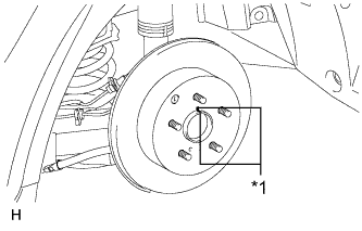
Text in Illustration *1 Matchmark Align the matchmarks of the disc and axle hub and install the disc.
Note
When replacing the rear disc with a new one, select an installation position where the rear disc has the smallest runout.
-
-
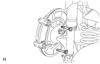
INSTALL REAR DISC BRAKE CYLINDER MOUNTING
-
Install the rear disc brake cylinder mounting to the axle carrier with the 2 bolts.
- Torque:
- 72 N*m { 734 kgf*cm, 53 ft.*lbf }
-
-
INSTALL REAR DISC BRAKE BUSH DUST BOOT
-
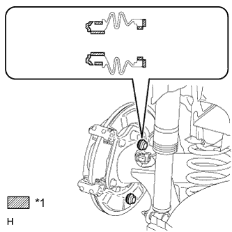
Text in Illustration *1 Lithium soap base glycol grease Apply a light coat of lithium soap base glycol grease to the entire circumference of 2 new rear disc brake bush dust boots where they contact the rear disc brake cylinder mounting, and the entire inner circumference of both ends of the boots.
Tech Tips
Apply at least 0.3 g (0.01 oz.) of lithium soap base glycol grease to the rear disc brake bush dust boot.
Note
Apply a sufficient amount of lithium soap base glycol grease to the entire circumference of the rear disc brake bush dust boot and rear disc brake cylinder mounting contact surfaces.
-
Install the 2 rear disc brake bush dust boots to the rear disc brake cylinder mounting.
-
-
INSTALL REAR DISC BRAKE CYLINDER SLIDE BUSH
-
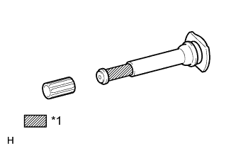
Text in Illustration *1 Lithium soap base glycol grease Apply a light coat of lithium soap base glycol grease to the rear disc brake cylinder slide pin as shown in the illustration.
-
Install a new rear disc brake cylinder slide bush to the rear disc brake cylinder slide pin.
-
-
INSTALL REAR DISC BRAKE CYLINDER SLIDE PIN
-
Text in Illustration *1 Lithium soap base glycol grease Apply a light coat of lithium soap base glycol grease to the sliding part and the seal surface of the 2 rear disc brake cylinder slide pins.
-
Install the 2 rear disc brake cylinder slide pins to the rear disc brake cylinder mounting.
-
-
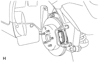
INSTALL REAR DISC BRAKE PAD SUPPORT PLATE
-
Install the 4 rear disc brake pad support plates to the rear disc brake cylinder mounting.
Note
Be sure to install each rear disc brake pad support plate in the correct position and direction.
-
-
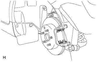
INSTALL REAR DISC BRAKE PAD
-
Install the 2 rear disc brake pads to the rear disc brake cylinder mounting.
Note
Make sure there is no oil or grease on the friction surfaces of the disc brake pads or the rear disc.
-
-
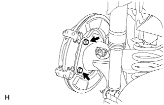
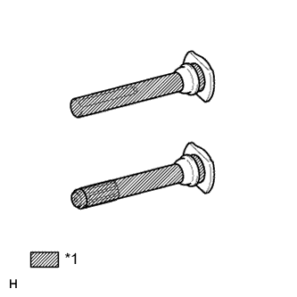
INSTALL REAR DISC BRAKE CYLINDER ASSEMBLY
-
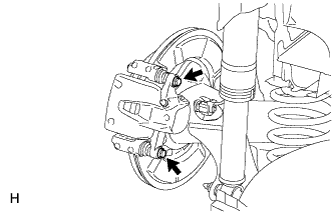
Hold the rear disc brake cylinder slide pins and install the rear disc brake cylinder assembly to the rear disc brake cylinder mounting with 2 new bolts.
- Torque:
- 30 N*m { 306 kgf*cm, 22 ft.*lbf }
-
-
CONNECT REAR BRAKE FLEXIBLE HOSE
-
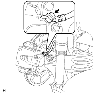
Install a new rear flexible hose gasket and connect the flexible hose to the rear disc brake cylinder assembly with a new union bolt.
- Torque:
- 29 N*m { 296 kgf*cm, 21 ft.*lbf }
Tech Tips
Insert the flexible hose lock securely into the lock hole in the disc brake cylinder.
-
-
ADJUST PARKING BRAKE SHOE CLEARANCE
-
Remove the console box assembly Click here.
-
Completely release the parking brake lever.
-
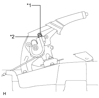
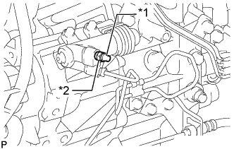
Text in Illustration *1 Lock Nut *2 Adjusting Nut Loosen the lock nut and adjusting nut to completely release the parking brake cable.
-
Temporarily install the hub nuts.
-
Remove the shoe adjusting hole plug.
-
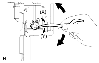
Insert an adjustment tool into the adjustment hole of the disc. Rotate the adjustment wheel in the "X" direction until the shoes are locked. Then rotate the adjustment wheel in the "Y" direction 8 notches.
-
Check that the disc can be rotated lightly. If not, rotate the adjustment wheel in the "Y" direction and check again.
-
Install the hole plug.
-
Remove the hub nuts.
-
Turn the adjusting nut until the parking brake lever travel becomes correct.
Standard parking brake lever travel when pulled with a force of 200 N (20 kgf, 45 lbf) 6 to 9 clicks -
Using a wrench or equivalent, hold the adjusting nut and tighten the lock nut.
- Torque:
- 6.0 N*m { 61 kgf*cm, 53 in.*lbf }
-
Operate the parking brake lever 3 to 4 times, and check the parking brake lever travel.
Standard parking brake lever travel when pulled with a force of 200 N (20 kgf, 45 lbf) 6 to 9 clicks -
Check whether the parking brake drags or not.
-
Operate the parking brake lever and check the illumination condition of the brake warning light.
OK The brake warning light always illuminates at the first click. -
Install the console box assembly Click here.
-
-
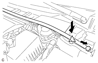
REMOVE CENTER COWL TOP VENTILATOR LOUVER
-
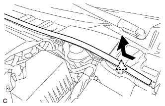
Slide the hood to cowl top seal and detach the clip as shown in the illustration.
-
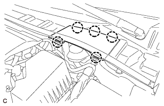
Detach the 5 claws and remove the center cowl top ventilator louver.
-
-
BLEED BRAKE LINE
-
Bleed brake line
-
Remove the brake master cylinder reservoir filler cap assembly.
-
Add brake fluid to keep the level between the MIN and MAX lines of the reservoir while bleeding the brakes.
Brake fluid SAE J1704 or FMVSS No, 116 DOT 4 -
Remove the bleeder plug cap.
-
Connect a vinyl tube to the bleeder plug.
-
Depress the brake pedal several times, and then loosen the bleeder plug with the pedal depressed.*1
-
When fluid stops coming out, tighten the bleeder plug, and then release the brake pedal.*2
-
Repeat *1 and *2 until all the air in the fluid is completely bled out.
-
Tighten the bleeder plug completely.
- Torque:
- 10 N*m { 102 kgf*cm, 7 ft.*lbf }
-
Install the bleeder plug cap.
-
Repeat the above procedure for each wheel to bleed the brake line.
-
-
Inspect fluid level Click here.
-
Inspect for brake fluid leak.
-
-
BLEED AIR FROM CLUTCH LINE (for 1ZR-FAE with Manual Transaxle)
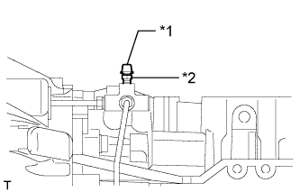
Text in Illustration *1 Bleeder Plug Cap *2 Bleeder Plug
-
Add brake fluid to keep the level between the MIN and MAX lines of the reservoir while bleeding the brakes.
Brake fluid SAE J1704 or FMVSS No, 116 DOT 4 -
Remove the bleeder plug cap.
-
Connect a vinyl tube to the bleeder plug.
-
Depress the clutch pedal 5 times, and then loosen the bleeder plug while the pedal is depressed.
-
When fluid no longer comes out, tighten the bleeder plug, and then release the clutch pedal.
-
Repeat both of the previous 2 steps 6 times.
-
Tighten the bleeder plug.
- Torque:
- 8.4 N*m { 86 kgf*cm, 74 in.*lbf }
-
Depress the clutch pedal 10 times or more and confirm its operation.
Note
This must be performed before the engine is started.
-
Install the bleeder plug cap.
-
Check that all the air has been bled from the clutch line.
-
-
BLEED AIR FROM CLUTCH LINE (for 2ZR-FAE with Manual Transaxle)
Text in Illustration *1 Bleeder Plug Cap *2 Bleeder Plug
-
Add brake fluid to keep the level between the MIN and MAX lines of the reservoir while bleeding the brakes.
Brake fluid SAE J1704 or FMVSS No, 116 DOT 4 -
Remove the bleeder plug cap.
-
Connect a vinyl tube to the bleeder plug.
-
Depress the clutch pedal 5 times, and then loosen the bleeder plug while the pedal is depressed.
-
When fluid no longer comes out, tighten the bleeder plug, and then release the clutch pedal.
-
Repeat both of the previous 2 steps 6 times.
-
Tighten the bleeder plug.
- Torque:
- 8.4 N*m { 86 kgf*cm, 74 in.*lbf }
-
Depress the clutch pedal 10 times or more and confirm its operation.
Note
This must be performed before the engine is started.
-
Install the bleeder plug cap.
-
Check that all the air has been bled from the clutch line.
-
-
BLEED CLUTCH LINE (for 1WW)
-
Add brake fluid to keep the level between the MIN and MAX lines of the reservoir while bleeding the brakes.
Brake fluid SAE J1704 or FMVSS No, 116 DOT 4 -
Text in Illustration *1 Bleeder Plug Cap *2 Bleeder Plug Remove the bleeder plug cap.
-
Connect a vinyl tube to the bleeder plug.
-
Depress the clutch pedal several times, and then loosen the bleeder plug while the pedal is depressed.
-
When fluid no longer comes out, tighten the bleeder plug, and then release the clutch pedal.
-
Repeat the previous 2 steps until all the air in the fluid is completely bled.
-
Tighten the bleeder plug.
- Torque:
- 11 N*m { 112 kgf*cm, 8 ft.*lbf }
-
Install the bleeder plug cap.
-
Check that all the air has been bled from the clutch line.
-
-
INSTALL CENTER COWL TOP VENTILATOR LOUVER
-
Attach the 5 claws to install the center cowl top ventilator louver.
-
Push the clip to attach it, and then slide the hood to cowl top seal as shown in the illustration to attach the claw.
-
-
INSTALL REAR WHEEL
- Torque:
- 103 N*m { 1050 kgf*cm, 76 ft.*lbf }