FRONT BRAKE FLEXIBLE HOSE INSTALLATION

Tech Tips
-
Use the same procedure for the RH and LH sides.
-
The following procedure is for the LH side.
Note
-
Because the left and right hoses are not interchangeable, verify the part number when installing the flexible hoses.
-
If the hoses are to be reused, connect them after checking the identification marks placed when each hose was removed.
-
INSTALL FRONT FLEXIBLE HOSE
-
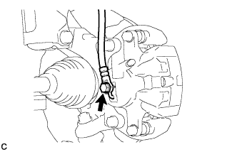
Install a new gasket and connect the front flexible hose to the disc brake cylinder assembly with a new union bolt.
- Torque:
- 29 N*m { 296 kgf*cm, 21 ft.*lbf }
Tech Tips
Insert the flexible hose lock securely into the lock hole in the disc brake cylinder.
-
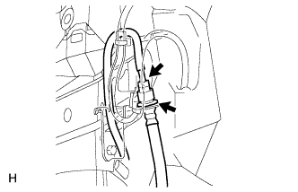
Install a new clip to the front flexible hose.
Note
Make sure the clip is completely pushed in.
-
Using a union nut wrench, connect the brake line to the front flexible hose while holding the flexible hose with a wrench.
- Torque:
- 15 N*m { 155 kgf*cm, 11 ft.*lbf }
Note
-
Do not kink or damage the brake line.
-
Do not allow any foreign matter such as dirt or dust to enter the brake line.
-
Use the formula to calculate special torque values for situations where a union nut wrench is combined with a torque wrench Click here.
-
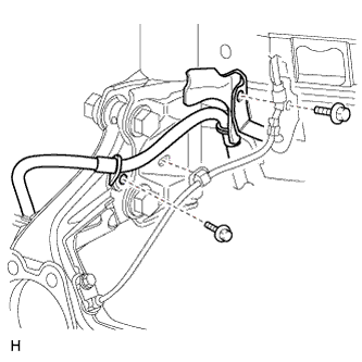
Install the front flexible hose and speed sensor harness bracket to the absorber bracket and steering knuckle with the 2 bolts.
- Torque:
- 29 N*m { 296 kgf*cm, 21 ft.*lbf }
Tech Tips
Install the front flexible hose first, and then install the speed sensor harness bracket.
-
-
REMOVE CENTER COWL TOP VENTILATOR LOUVER
-
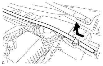
Slide the hood to cowl top seal and detach the clip as shown in the illustration.
-
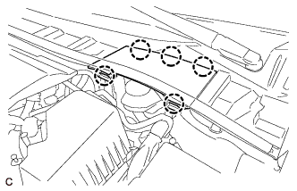
Detach the 5 claws and remove the center cowl top ventilator louver.
-
-
BLEED BRAKE LINE
-
Bleed brake line
-
Remove the brake master cylinder reservoir filler cap assembly.
-
Add brake fluid to keep the level between the MIN and MAX lines of the reservoir while bleeding the brakes.
Brake fluid SAE J1704 or FMVSS No, 116 DOT 4 -
Remove the bleeder plug cap.
-
Connect a vinyl tube to the bleeder plug.
-
Depress the brake pedal several times, and then loosen the bleeder plug with the pedal depressed.*1
-
When fluid stops coming out, tighten the bleeder plug, and then release the brake pedal.*2
-
Repeat *1 and *2 until all the air in the fluid is completely bled out.
-
Tighten the bleeder plug completely.
- Torque:
- 10 N*m { 102 kgf*cm, 7 ft.*lbf }
-
Install the bleeder plug cap.
-
Repeat the above procedure for each wheel to bleed the brake line.
-
-
Inspect fluid level Click here.
-
Inspect for brake fluid leak.
-
-
BLEED AIR FROM CLUTCH LINE (for 1ZR-FAE with Manual Transaxle)
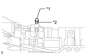
Text in Illustration *1 Bleeder Plug Cap *2 Bleeder Plug
-
Add brake fluid to keep the level between the MIN and MAX lines of the reservoir while bleeding the brakes.
Brake fluid SAE J1704 or FMVSS No, 116 DOT 4 -
Remove the bleeder plug cap.
-
Connect a vinyl tube to the bleeder plug.
-
Depress the clutch pedal 5 times, and then loosen the bleeder plug while the pedal is depressed.
-
When fluid no longer comes out, tighten the bleeder plug, and then release the clutch pedal.
-
Repeat both of the previous 2 steps 6 times.
-
Tighten the bleeder plug.
- Torque:
- 8.4 N*m { 86 kgf*cm, 74 in.*lbf }
-
Depress the clutch pedal 10 times or more and confirm its operation.
Note
This must be performed before the engine is started.
-
Install the bleeder plug cap.
-
Check that all the air has been bled from the clutch line.
-
-
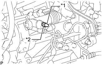
BLEED AIR FROM CLUTCH LINE (for 2ZR-FAE with Manual Transaxle)
Text in Illustration *1 Bleeder Plug Cap *2 Bleeder Plug
-
Add brake fluid to keep the level between the MIN and MAX lines of the reservoir while bleeding the brakes.
Brake fluid SAE J1704 or FMVSS No, 116 DOT 4 -
Remove the bleeder plug cap.
-
Connect a vinyl tube to the bleeder plug.
-
Depress the clutch pedal 5 times, and then loosen the bleeder plug while the pedal is depressed.
-
When fluid no longer comes out, tighten the bleeder plug, and then release the clutch pedal.
-
Repeat both of the previous 2 steps 6 times.
-
Tighten the bleeder plug.
- Torque:
- 8.4 N*m { 86 kgf*cm, 74 in.*lbf }
-
Depress the clutch pedal 10 times or more and confirm its operation.
Note
This must be performed before the engine is started.
-
Install the bleeder plug cap.
-
Check that all the air has been bled from the clutch line.
-
-
BLEED CLUTCH LINE (for 1WW)
-
Add brake fluid to keep the level between the MIN and MAX lines of the reservoir while bleeding the brakes.
Brake fluid SAE J1704 or FMVSS No, 116 DOT 4 -
Text in Illustration *1 Bleeder Plug Cap *2 Bleeder Plug Remove the bleeder plug cap.
-
Connect a vinyl tube to the bleeder plug.
-
Depress the clutch pedal several times, and then loosen the bleeder plug while the pedal is depressed.
-
When fluid no longer comes out, tighten the bleeder plug, and then release the clutch pedal.
-
Repeat the previous 2 steps until all the air in the fluid is completely bled.
-
Tighten the bleeder plug.
- Torque:
- 11 N*m { 112 kgf*cm, 8 ft.*lbf }
-
Install the bleeder plug cap.
-
Check that all the air has been bled from the clutch line.
-
-
INSTALL CENTER COWL TOP VENTILATOR LOUVER
-
Attach the 5 claws to install the center cowl top ventilator louver.
-
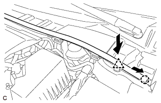
Push the clip to attach it, and then slide the hood to cowl top seal as shown in the illustration to attach the claw.
-
-
INSTALL FRONT WHEEL
- Torque:
- 103 N*m { 1050 kgf*cm, 76 ft.*lbf }