BRAKE MASTER CYLINDER INSTALLATION

-
INSTALL BRAKE MASTER CYLINDER SUB-ASSEMBLY
-
Install a new O-ring to the brake master cylinder sub-assembly.
-
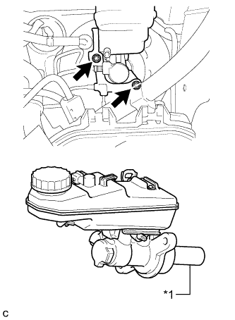
Text in Illustration *1 Piston Install the brake master cylinder with the 2 new nuts.
- Torque:
- 20 N*m { 204 kgf*cm, 15 ft.*lbf }
Note
-
The master cylinder requires careful handling. Do not allow the master cylinder to receive any impact, such as from being dropped. Do not reuse a master cylinder that has been dropped.
-
Do not strike or pinch the master cylinder piston, and do not cause any damage to the master cylinder piston by any other means.
-
When installing the master cylinder to the brake booster, or when removing the master cylinder from the brake booster, make sure that the master cylinder is kept horizontal or with its tip facing downward (the piston faces upward) to prevent the master cylinder piston from falling out.
-
Do not allow any foreign objects to contaminate the master cylinder piston. If a foreign object gets on the piston, remove it by using a piece of cloth and then apply an even layer of lithium soap base glycol grease around the circumference (sliding part) of the piston.
-
Do not use any other type of grease or fluid.
-
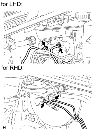
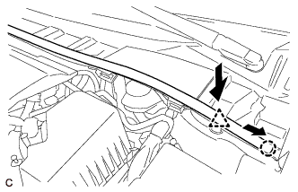
Using a union nut wrench, connect the 2 brake lines to the brake master cylinder sub-assembly.
- Torque:
- 20 N*m { 199 kgf*cm, 14 ft.*lbf }
Note
Use the formula to calculate special torque values for situations where a union nut wrench is combined with a torque wrench Click here.
-
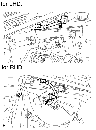
Attach the clamp and connect the connector.
-
-
CONNECT CLUTCH TUBE (for Manual Transaxle)
-
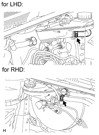
Connect the clutch tube to the brake master cylinder reservoir assembly with the clip.
-
-
INSTALL BRAKE ACTUATOR ASSEMBLY
-
Install the brake actuator sub-assembly Click here.
-
-
INSTALL OUTER COWL TOP PANEL SUB-ASSEMBLY (for 1ZR-FAE)
-
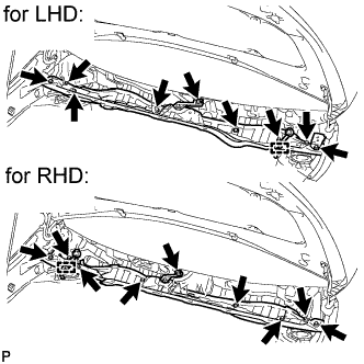
Install the outer cowl top panel with the 9 bolts.
- Torque:
- 8.8 N*m { 90 kgf*cm, 78 in.*lbf }
-
Connect the connector clamp.
-
-
INSTALL OUTER COWL TOP PANEL SUB-ASSEMBLY (for 2ZR-FAE)
-
Install the outer cowl top panel with the 9 bolts.
- Torque:
- 8.8 N*m { 90 kgf*cm, 78 in.*lbf }
-
Connect the connector clamp.
-
-
INSTALL OUTER COWL TOP PANEL SUB-ASSEMBLY (for 1AD-FTV)
-
Install the cowl top panel with the 9 bolts.
- Torque:
- 8.8 N*m { 90 kgf*cm, 78 in.*lbf }
-
-
INSTALL OUTER COWL TOP PANEL SUB-ASSEMBLY (for 2AD-FHV)
-
Install the outer cowl top panel with the 9 bolts.
- Torque:
- 8.8 N*m { 90 kgf*cm, 78 in.*lbf }
-
-
INSTALL WINDSHIELD WIPER MOTOR AND LINK
-
Install the windshield wiper motor and link Click here.
-
-
INSTALL NO. 2 CYLINDER HEAD COVER (for 1ZR-FAE)
-
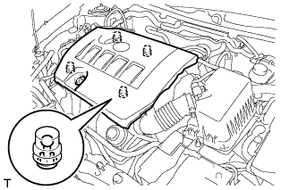
Attach the 4 clips to install the cover.
Note
-
Be sure to attach the clips securely.
-
Do not apply excessive force or hit the cover to attach the clips. This may cause the cover to break.
-
-
-
INSTALL NO. 2 CYLINDER HEAD COVER (for 2ZR-FAE)
-
Attach the 4 clips to install the cover.
Note
-
Be sure to attach the clips securely.
-
Do not apply excessive force or hit the cover to attach the clips. This may cause the cover to break.
-
-
-
INSTALL FUEL FILTER ELEMENT ASSEMBLY
-
for 1AD-FTV:
Install the fuel filter element assembly Click here.
-
for 2AD-FHV:
Install the fuel filter element assembly Click here.
-
-
REMOVE CENTER COWL TOP VENTILATOR LOUVER
-
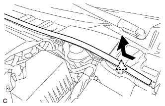
Slide the hood to cowl top seal and detach the clip as shown in the illustration.
-
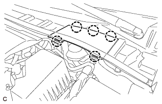
Detach the 5 claws and remove the center cowl top ventilator louver.
-
-
BLEED BRAKE SYSTEM
-
Bleed brake master cylinder
Note
-
If the master cylinder is reinstalled or if the reservoir becomes empty, bleed the master cylinder.
-
To prevent brake fluid from damaging painted surfaces, cover any surrounding parts with a piece of cloth.
-
Remove the brake master cylinder reservoir filler cap assembly.
-
Add brake fluid to keep the level between the MIN and MAX lines of the reservoir while bleeding the brakes.
Brake fluid SAE J1704 or FMVSS No, 116 DOT 4 -
Using a union nut wrench, disconnect the 2 brake lines from the master cylinder.
-
Slowly depress the brake pedal and hold it.*1
-
Cover the 2 outer holes with fingers and release the brake pedal.*2
-
Repeat *1 and *2 3 or 4 times.
-
Using a union nut wrench, connect the 2 brake lines to the master cylinder.
- Torque:
- 20 N*m { 199 kgf*cm, 14 ft.*lbf }
Note
Use the formula to calculate special torque values for situations where a union nut wrench is combined with a torque wrench Click here.
-
-
Bleed brake line
-
Remove the bleeder plug cap.
-
Connect a vinyl tube to the bleeder plug.
-
Depress the brake pedal several times, and then loosen the bleeder plug with the pedal depressed.*1
-
When fluid stops coming out, tighten the bleeder plug, and then release the brake pedal.*2
-
Repeat *1 and *2 until all the air in the fluid is completely bled out.
-
Tighten the bleeder plug completely.
- Torque:
- 10 N*m { 102 kgf*cm, 7 ft.*lbf }
-
Install the bleeder plug cap.
-
Repeat the above procedure for each wheel to bleed the brake line.
-
-
Bleed brake actuator (w/ VSC)
Note
After bleeding the brake system, if the specified height or feel of the brake pedal cannot be obtained, bleed the brake actuator assembly with the intelligent tester by following the procedure below.
-
Depress the brake pedal more than 20 times with the ignition switch off.
-
Connect the intelligent tester to the DLC3.
-
Turn the ignition switch to ON.
Note
Do not start the engine.
-
Enter the following menus: Chassis / ABS/VSC/TRC / Utility / Air Bleeding.
Tech Tips
Refer to the intelligent tester operator's manual for further details.
-
Bleed the front right brake line.
Note
Make sure that the master cylinder reservoir does not run out of brake fluid.
1. Select "FR Line" on the intelligent tester.
2. Loosen the bleeder plug.
3. Depress the brake pedal and hold it.
Note
The actuator operation stops automatically in 4 seconds.
4. Tighten the bleeder plug completely.
- Torque:
- 10 N*m { 102 kgf*cm, 7 ft.*lbf }
5. Release the brake pedal.
6. Wait 20 seconds.
7. Repeat the steps above until there are no more air bubbles in the fluid.
-
Bleed the front left brake line.
Note
Make sure that the master cylinder reservoir does not run out of brake fluid.
1. Select "FL Line" on the intelligent tester.
2. Loosen the bleeder plug.
3. Depress the brake pedal and hold it.
Note
The actuator operation stops automatically in 4 seconds.
4. Tighten the bleeder plug completely.
- Torque:
- 10 N*m { 102 kgf*cm, 7 ft.*lbf }
5. Release the brake pedal.
6. Wait 20 seconds.
7. Repeat the steps above until there are no more air bubbles in the fluid.
-
Bleed the rear right brake line.
Note
Make sure that the master cylinder reservoir does not run out of brake fluid.
1. Select "RR Line" on the intelligent tester.
2. Loosen the bleeder plug.
3. Depress the brake pedal and hold it.
Note
The actuator operation stops automatically in 4 seconds.
4. Tighten the bleeder plug completely.
- Torque:
- 10 N*m { 102 kgf*cm, 7 ft.*lbf }
5. Release the brake pedal.
6. Wait 20 seconds.
7. Repeat the steps above until there are no more air bubbles in the fluid.
-
Bleed the rear left brake line.
Note
Make sure that the master cylinder reservoir does not run out of brake fluid.
1. Select "RL Line" on the intelligent tester.
2. Loosen the bleeder plug.
3. Depress the brake pedal and hold it.
Note
The actuator operation stops automatically in 4 seconds.
4. Tighten the bleeder plug completely.
- Torque:
- 10 N*m { 102 kgf*cm, 7 ft.*lbf }
5. Release the brake pedal.
6. Wait 20 seconds.
7. Repeat the steps above until there are no more air bubbles in the fluid.
-
Disconnect the intelligent tester from the DLC3.
-
-
Clear the DTCs Click here.
-
Inspect for brake fluid leak.
-
Inspect fluid level in reservoir Click here.
-
-
BLEED AIR FROM CLUTCH LINE (for 1ZR-FAE with Manual Transaxle)
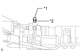
Text in Illustration *1 Bleeder Plug Cap *2 Bleeder Plug
-
Add brake fluid to keep the level between the MIN and MAX lines of the reservoir while bleeding the brakes.
Brake fluid SAE J1704 or FMVSS No, 116 DOT 4 -
Remove the bleeder plug cap.
-
Connect a vinyl tube to the bleeder plug.
-
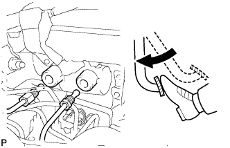
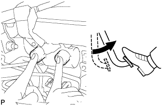
Depress the clutch pedal 5 times, and then loosen the bleeder plug while the pedal is depressed.
-
When fluid no longer comes out, tighten the bleeder plug, and then release the clutch pedal.
-
Repeat both of the previous 2 steps 6 times.
-
Tighten the bleeder plug.
- Torque:
- 8.4 N*m { 86 kgf*cm, 74 in.*lbf }
-
Depress the clutch pedal 10 times or more and confirm its operation.
Note
This must be performed before the engine is started.
-
Install the bleeder plug cap.
-
Check that all the air has been bled from the clutch line.
-
-
BLEED AIR FROM CLUTCH LINE (for 2ZR-FAE with Manual Transaxle)
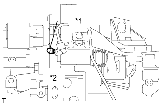
Text in Illustration *1 Bleeder Plug Cap *2 Bleeder Plug
-
Add brake fluid to keep the level between the MIN and MAX lines of the reservoir while bleeding the brakes.
Brake fluid SAE J1704 or FMVSS No, 116 DOT 4 -
Remove the bleeder plug cap.
-
Connect a vinyl tube to the bleeder plug.
-
Depress the clutch pedal 5 times, and then loosen the bleeder plug while the pedal is depressed.
-
When fluid no longer comes out, tighten the bleeder plug, and then release the clutch pedal.
-
Repeat both of the previous 2 steps 6 times.
-
Tighten the bleeder plug.
- Torque:
- 8.4 N*m { 86 kgf*cm, 74 in.*lbf }
-
Depress the clutch pedal 10 times or more and confirm its operation.
Note
This must be performed before the engine is started.
-
Install the bleeder plug cap.
-
Check that all the air has been bled from the clutch line.
-
-
BLEED AIR FROM CLUTCH LINE (for 1AD-FTV with Manual Transaxle)
Text in Illustration *1 Bleeder Plug Cap *2 Bleeder Plug
-
Add brake fluid to keep the level between the MIN and MAX lines of the reservoir while bleeding the brakes.
Brake fluid SAE J1704 or FMVSS No, 116 DOT 4 -
Remove the bleeder plug cap.
-
Connect a vinyl tube to the bleeder plug.
-
Depress the clutch pedal several times, and then loosen the bleeder plug while the pedal is depressed.
-
When fluid no longer comes out, tighten the bleeder plug, and then release the clutch pedal.
-
Repeat the previous 2 steps until all the air in the fluid is completely bled.
-
Tighten the bleeder plug.
- Torque:
- 8.4 N*m { 86 kgf*cm, 74 in.*lbf }
-
Install the bleeder plug cap.
-
Check that all the air has been bled from the clutch line.
-
-
BLEED AIR FROM CLUTCH LINE (for 2AD-FHV with Manual Transaxle)
Text in Illustration *1 Bleeder Plug Cap *2 Bleeder Plug
-
Add brake fluid to keep the level between the MIN and MAX lines of the reservoir while bleeding the brakes.
Brake fluid SAE J1704 or FMVSS No, 116 DOT 4 -
Remove the bleeder plug cap.
-
Connect a vinyl tube to the bleeder plug.
-
Depress the clutch pedal several times, and then loosen the bleeder plug while the pedal is depressed.
-
When fluid no longer comes out, tighten the bleeder plug, and then release the clutch pedal.
-
Repeat the previous 2 steps until all the air in the fluid is completely bled.
-
Tighten the bleeder plug.
- Torque:
- 8.4 N*m { 86 kgf*cm, 74 in.*lbf }
-
Install the bleeder plug cap.
-
Check that all the air has been bled from the clutch line.
-
-
INSTALL CENTER COWL TOP VENTILATOR LOUVER
-
Attach the 5 claws to install the center cowl top ventilator louver.
-
Push the clip to attach it, and then slide the hood to cowl top seal as shown in the illustration to attach the claw.
-