- Click here
REMOVE BRAKE ACTUATOR COVER (for 1WW)
-
Install a new brake actuator cover to the brake actuator assembly.
-
- Click here
INSTALL BRAKE ACTUATOR ASSEMBLY WITH BRACKET
-
for Manual Transaxle:
-
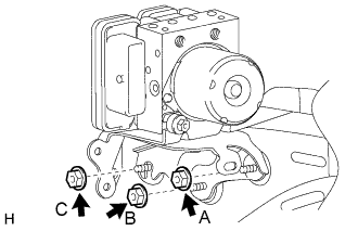
Install the brake actuator with bracket with the 3 nuts. Tighten the 3 nuts uniformly in alphabetical order.
19 N*m 194 kgf*cm 14 ft.*lbf Note:
-
Be careful not to damage the brake tubes and wire harness.
-
Do not drop the actuator. If dropped, replace it.
-
-
-
for CVT:
-
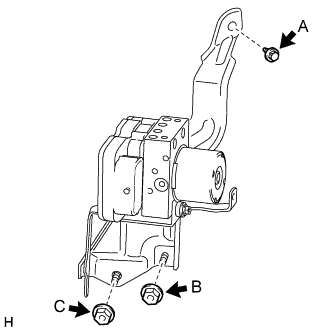
Install the brake actuator with bracket with the 2 nuts and bolt. Tighten the 2 nuts and bolt uniformly in alphabetical order.
19 N*m 194 kgf*cm 14 ft.*lbf Note:
-
Be careful not to damage the brake tubes and wire harness.
-
Do not drop the actuator. If dropped, replace it.
-
-
-
for Manual Transaxle:
-
Install 2 new tube clamps to the tubes, and then attach the 2 clamps to the brake actuator bracket.
-
-
for CVT:
-
Install 2 new tube clamps to the tubes, and then attach the 2 clamps to the brake actuator bracket.
-
-
- Click here
CONNECT BRAKE LINE
-
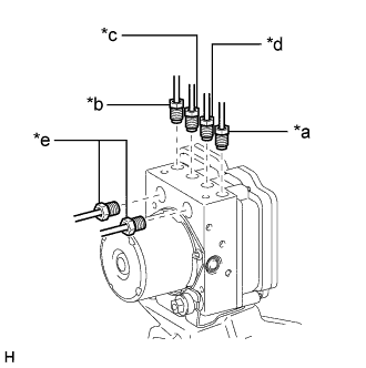
Set each brake line in the correct position on the brake actuator as shown in the illustration.
Table 1. Text in Illustration *a to Front Wheel Cylinder RH *b to Front Wheel Cylinder LH *c to Rear Wheel Cylinder RH *d to Rear Wheel Cylinder LH *e From Master Cylinder -
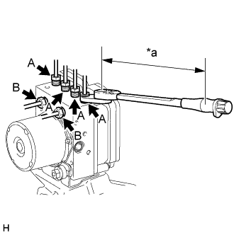
Using a union nut wrench, connect the 6 brake lines to the brake actuator.
for flare nut A 15 N*m 155 kgf*cm 11 ft.*lbf for flare nut B 20 N*m 199 kgf*cm 14 ft.*lbf Table 2. Text in Illustration *a Torque Wrench Fulcrum Length Tip:
-
Calculate the torque wrench reading when changing the fulcrum length of the torque wrench (Click here).
-
for flare nut A
When using a union nut wrench (fulcrum length of 22 mm (0.8661 in.)) + torque wrench (fulcrum length of 162 mm (6.3779 in.)): 13 N*m (137 kgf*cm, 10 ft.*lbf).
-
for flare nut B
When using a union nut wrench (fulcrum length of 20 mm (0.7874 in.)) + torque wrench (fulcrum length of 180 mm (7.0866 in.)): 18 N*m (179 kgf*cm, 13 ft.*lbf).
-
-
- Click here
CONNECT CONNECTOR
-
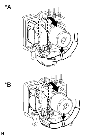
Connect the connector, attach the harness clamp and push the lock lever downward.
Table 3. Text in Illustration *A for Manual Transaxle *B for CVT
-
- Click here
INSTALL AIR CLEANER CASE SUB-ASSEMBLY
-
for 1ZR-FAE:
Install the air cleaner case sub-assembly (Click here).
-
for 2ZR-FAE:
Install the air cleaner case sub-assembly (Click here).
-
- Click here
INSTALL FUEL FILTER ASSEMBLY (for 1WW)
-
Install the fuel filter assembly (Click here).
-
- Click here
CONNECT CABLE TO NEGATIVE BATTERY TERMINAL
Note:When disconnecting the cable, some systems need to be initialized after the cable is reconnected (Click here).
- Click here
REMOVE CENTER COWL TOP VENTILATOR LOUVER
-
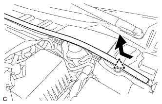
Slide the hood to cowl top seal and detach the clip as shown in the illustration.
-
Detach the 5 claws and remove the center cowl top ventilator louver.
-
- Click here
BLEED BRAKE SYSTEM
- Click here
BLEED AIR FROM CLUTCH LINE (for 1ZR-FAE with Manual Transaxle)
- Click here
BLEED AIR FROM CLUTCH LINE (for 2ZR-FAE with Manual Transaxle)
- Click here
BLEED AIR FROM CLUTCH LINE (for 1WW with Manual Transaxle)
- Click here
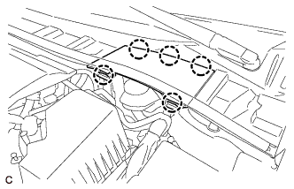
INSTALL CENTER COWL TOP VENTILATOR LOUVER
-
Attach the 5 claws to install the center cowl top ventilator louver.
-
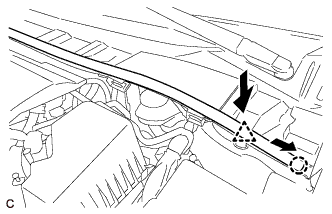
Push the clip to attach it, and then slide the hood to cowl top seal as shown in the illustration to attach the claw.
-
- Click here
CHECK BRAKE ACTUATOR ASSEMBLY WITH GTS