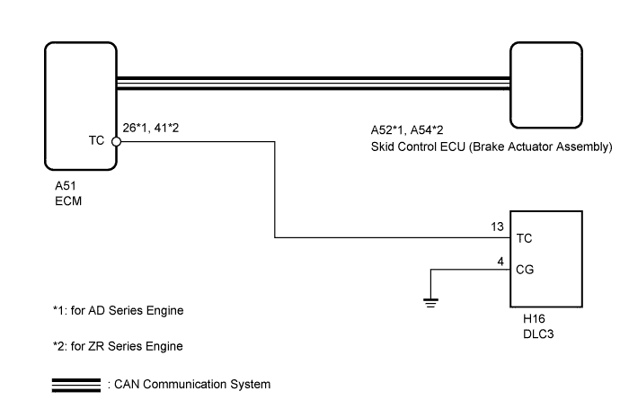
VEHICLE STABILITY CONTROL SYSTEM TC and CG Terminal Circuit
DESCRIPTION
Connecting terminals TC and CG of the DLC3 causes the ECU to display the DTCs by blinking the ABS warning light and by displaying the code in the multi-information display.
WIRING DIAGRAM
INSPECTION PROCEDURE
Note
When replacing the skid control ECU (brake actuator assembly), perform the engine variant learning Click here.
Tech Tips
When the warning lights continue to blink, there may be a ground short in the wiring of terminal TC of the DLC3 or an internal ground short in one or more ECUs.
PROCEDURE
-
CHECK CAN COMMUNICATION SYSTEM
-
Check if a CAN communication system DTC is output Click here.
Result Result Proceed to CAN communication system DTC is not output. A CAN communication system DTC is output. B
B 
GO TO CAN COMMUNICATION SYSTEM (HOW TO PROCEED WITH TROUBLESHOOTING) Click here
A 
-
-
INSPECT DLC3
-
Turn the ignition switch to ON.
-
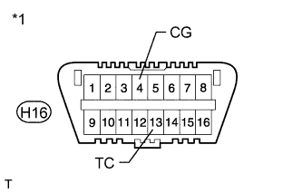
Text in Illustration *1 Front view of DLC3 Measure the voltage according to the value(s) in the table below.
Standard Voltage Tester Connection Switch Condition Specified Condition H16-13 (TC) - H16-4 (CG) Ignition switch ON 11 to 14 V
NG 
CHECK HARNESS AND CONNECTOR (TC OF DLC3 - ECM) Click here
OK
-
-
CHECK ECM (TC OF DLC3 INPUT)
-
Turn the ignition switch off.
-
Text in Illustration *1 Front view of DLC3 Using SST, connect terminals 13 (TC) and 4 (CG) of the DLC3.
- SST
- 09843-18040
-
Turn the ignition switch to ON.
-
Check that the MIL is blinking.
Result Result Proceed to MIL is blinking. A MIL is not blinking. B Tech Tips
-
If troubleshooting has been carried out according to the Problem Symptoms Table, refer back to the table and proceed to the next step before replacing the part Click here.
-
Refer to the ECM installation procedures:
-
for 1ZR-FAE Click here
-
for 2ZR-FAE Click here
-
for 1AD-FTV Click here
-
for 2AD-FHV Click here
-
B
REPLACE ECM
A 
REPLACE BRAKE ACTUATOR ASSEMBLY Click here
-
-
CHECK HARNESS AND CONNECTOR (TC OF DLC3 - ECM)
-
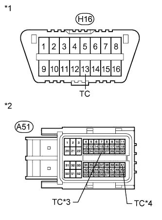
Text in Illustration *1 Front view of DLC3 *2 Front view of wire harness connector
(to ECM)
*3 for AD Series Engine *4 for ZR Series Engine Turn the ignition switch off.
-
Disconnect the ECM connector.
-
Measure the resistance according to the value(s) in the table below.
Standard Resistance for AD Series Engine Tester Connection Condition Specified Condition H16-13 (TC) - A51-26 (TC) Always Below 1 Ω H16-13 (TC) - Body ground Always 10 kΩ or higher for ZR Series Engine Tester Connection Condition Specified Condition H16-13 (TC) - A51-41 (TC) Always Below 1 Ω H16-13 (TC) - Body ground Always 10 kΩ or higher
NG
REPAIR OR REPLACE HARNESS OR CONNECTOR
OK
-
-
CHECK HARNESS AND CONNECTOR (CG OF DLC3 - BODY GROUND)
-
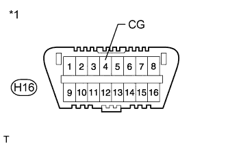
Text in Illustration *1 Front view of DLC3 Measure the resistance according to the value(s) in the table below.
Standard Resistance Tester Connection Condition Specified Condition H16-4 (CG) - Body ground Always Below 1 Ω
NG
REPAIR OR REPLACE HARNESS OR CONNECTOR
OK
-
-
CHECK ECM (TC OF DLC3 INPUT)
-
Turn the ignition switch off.
-
Text in Illustration *1 Front view of DLC3 Using SST, connect terminals 13 (TC) and 4 (CG) of the DLC3.
- SST
- 09843-18040
-
Turn the ignition switch to ON.
-
Check that the MIL is blinking.
Result Result Proceed to MIL is blinking. A MIL is not blinking. B Tech Tips
-
If troubleshooting has been carried out according to the Problem Symptoms Table, refer back to the table and proceed to the next step before replacing the part Click here.
-
Refer to the ECM installation procedures:
-
for 1ZR-FAE Click here
-
for 2ZR-FAE Click here
-
for 1AD-FTV Click here
-
for 2AD-FHV Click here
-
B
REPLACE ECM
A
REPLACE BRAKE ACTUATOR ASSEMBLY Click here
-