VEHICLE STABILITY CONTROL SYSTEM, Diagnostic DTC:C1380/64

| DTC Code | DTC Name |
|---|---|
| C1380/64 | Stop Light Control Relay Malfunction |
DESCRIPTION
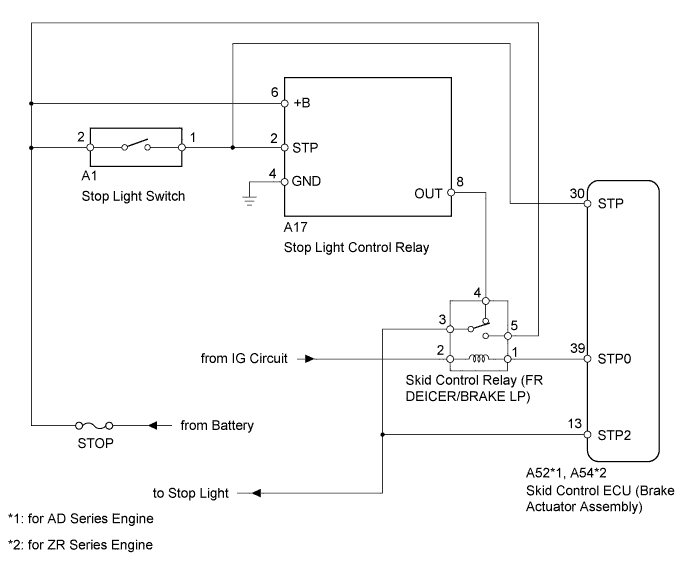
Upon receiving the hill-start assist control operating signal from the skid control ECU, the relay turns on and the stop light comes on.
| DTC Code | DTC Detection Condition | Trouble Area |
|---|---|---|
| C1380/64 | Either condition is met:
|
|
WIRING DIAGRAM
INSPECTION PROCEDURE
Note
-
When replacing the skid control ECU (brake actuator assembly), perform the engine variant learning Click here.
-
Inspect the fuses for circuits related to this system before performing the following inspection procedure.
Tech Tips
When DTC C1249/49 is output together with DTC C1380/64, inspect and repair the trouble areas indicated by DTC C1249/49 first Click here.
PROCEDURE
-
INSPECT SKID CONTROL RELAY (FR DEICER/BRAKE LP)
-
Remove the skid control relay from the engine room No. 1 relay block.
-
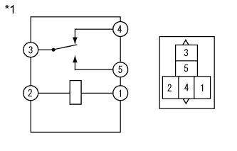
Text in Illustration *1 Skid Control Relay (FR DEICER/BRAKE LP Relay) Measure the resistance according to the value(s) in the table below.
Standard Resistance Tester Connection Condition Specified Condition 3 - 4 Battery voltage not applied to terminals 1 and 2 Below 1 Ω 3 - 5 Battery voltage not applied to terminals 1 and 2 10 kΩ or higher 3 - 4 Battery voltage applied to terminals 1 and 2 10 kΩ or higher 3 - 5 Battery voltage applied to terminals 1 and 2 Below 1 Ω
NG 
REPLACE SKID CONTROL RELAY
OK 
-
-
CHECK HARNESS AND CONNECTOR (ENGINE ROOM RELAY BLOCK SKID CONTROL RELAY TERMINAL)
-
Remove the skid control relay from the engine room No. 1 relay block.
-
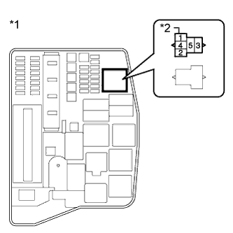
Text in Illustration *1 Engine Room No. 1 Relay Block *2 Skid Control Relay (FR DEICER/BRAKE LP) Measure the voltage according to the value(s) in the table below.
Standard Voltage Tester Connection Condition Specified Condition Relay block skid control relay terminal 5 - Body ground Always 11 to 14 V
NG
REPAIR OR REPLACE HARNESS OR CONNECTOR
OK
-
-
CHECK HARNESS AND CONNECTOR (ENGINE ROOM RELAY BLOCK SKID CONTROL RELAY TERMINAL)
-
Remove the skid control relay from the engine room No. 1 relay block.
-
Text in Illustration *1 Engine Room No. 1 Relay Block *2 Skid Control Relay (FR DEICER/BRAKE LP) Measure the voltage according to the value(s) in the table below.
Standard Voltage Tester Connection Switch Condition Specified Condition Relay block skid control relay terminal 4 - Body ground Stop light switch on (Brake pedal depressed) 8 to 14 V Stop light switch off (Brake pedal released) Below 1.5 V
NG 
CHECK HARNESS AND CONNECTOR (STOP LIGHT CONTROL RELAY - ENGINE ROOM RELAY BLOCK) Click here
OK
-
-
CHECK HARNESS AND CONNECTOR (SKID CONTROL ECU STP2 TERMINAL)
-
Disconnect the skid control ECU connector.
-
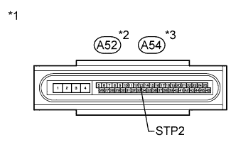
Text in Illustration *1 Front view of wire harness connector
(to Skid Control ECU)
*2 for AD Series Engine *3 for ZR Series Engine Measure the voltage according to the value(s) in the table below.
Standard Voltage Tester Connection Switch Condition Specified Condition A52 or A54-13 (STP2) - Body ground Stop light switch on (Brake pedal depressed) 8 to 14 V Stop light switch off (Brake pedal released) Below 1.5 V
NG
REPAIR OR REPLACE HARNESS OR CONNECTOR
OK
-
-
CHECK HARNESS AND CONNECTOR (SKID CONTROL ECU STP TERMINAL)
-
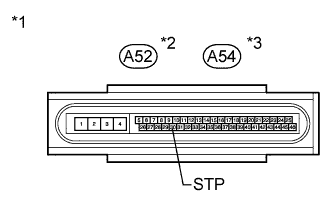
Text in Illustration *1 Front view of wire harness connector
(to Skid Control ECU)
*2 for AD Series Engine *3 for ZR Series Engine Disconnect the skid control ECU connector.
-
Measure the voltage according to the value(s) in the table below.
Standard Voltage Tester Connection Condition Specified Condition A52 or A54-30 (STP) - Body ground Stop light switch on (Brake pedal depressed) 8 to 14 V Stop light switch off (Brake pedal released) Below 1.5 V
NG
REPAIR OR REPLACE HARNESS OR CONNECTOR
OK
-
-
CHECK HARNESS AND CONNECTOR (SKID CONTROL ECU STP0 TERMINAL)
-
Disconnect the skid control ECU connector.
-
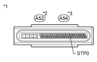
Text in Illustration *1 Front view of wire harness connector
(to Skid Control ECU)
*2 for AD Series Engine *3 for ZR Series Engine Measure the voltage according to the value(s) in the table below.
Standard Voltage Tester Connection Switch Condition Specified Condition A52 or A54-39 (STP0) - Body ground Ignition switch ON 11 to 14 V
NG
REPAIR OR REPLACE HARNESS OR CONNECTOR
OK
-
-
RECONFIRM DTC
-
Clear the DTCs Click here.
-
Start the engine.
-
Depress the brake pedal several times to test the stop light circuit.
-
Check if the same DTC is output Click here.
Result Result Proceed to DTC C1380/64 is output. A DTC C1380/64 is not output. B
B
USE SIMULATION METHOD TO CHECK Click here
A 
REPLACE BRAKE ACTUATOR ASSEMBLY Click here
-
-
CHECK HARNESS AND CONNECTOR (STOP LIGHT CONTROL RELAY - ENGINE ROOM RELAY BLOCK)
-
Disconnect the stop light control relay connector.
-
Remove the skid control relay from the engine room No. 1 relay block.
-
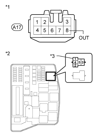
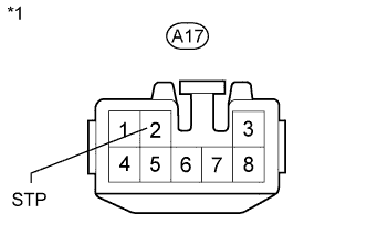
Text in Illustration *1 Front view of wire harness connector
(to Stop Light Control Relay)
*2 Engine Room No. 1 Relay Block *3 Skid Control Relay (FR DEICER/BRAKE LP) Measure the resistance according to the value(s) in the table below.
Standard Resistance Tester Connection Condition Specified Condition A17-8 (OUT) - Relay block skid control relay terminal 4 Always Below 1 Ω A17-8 (OUT) - Body ground Always 10 kΩ or higher
NG
REPAIR OR REPLACE HARNESS OR CONNECTOR
OK
-
-
CHECK HARNESS AND CONNECTOR (STOP LIGHT CONTROL RELAY +B, GND TERMINAL)
-
Disconnect the stop light control relay connector.
-
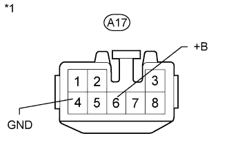
Text in Illustration *1 Front view of wire harness connector
(to Stop Light Control Relay)
Measure the voltage according to the value(s) in the table below.
Standard Voltage Tester Connection Condition Specified Condition A17-6 (+B) - Body ground Always 11 to 14 V -
Measure the resistance according to the value(s) in the table below.
Standard Resistance Tester Connection Condition Specified Condition A17-4 (GND) - Body ground Always Below 1Ω
NG
REPAIR OR REPLACE HARNESS OR CONNECTOR
OK
-
-
CHECK HARNESS AND CONNECTOR (STOP LIGHT CONTROL RELAY STP TERMINAL)
-
Disconnect the stop light control relay connector.
-
Text in Illustration *1 Front view of wire harness connector
(to Stop Light Control Relay)
Measure the voltage according to the value(s) in the table below.
Standard Voltage Tester Connection Switch Condition Specified Condition A17-2 (STP) - Body ground Stop light switch on (Brake pedal depressed) 8 to 14 V Stop light switch off (Brake pedal released) Below 1.5 V Result Result Proceed to NG A OK for LHD B OK for RHD C
B
REPLACE STOP LIGHT CONTROL RELAY Click here
C
REPLACE STOP LIGHT CONTROL RELAY Click here
A
REPAIR OR REPLACE HARNESS OR CONNECTOR
-