VEHICLE STABILITY CONTROL SYSTEM Slip Indicator Light Remains ON
DESCRIPTION
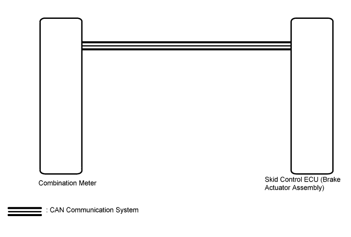
The skid control ECU is connected to the combination meter assembly via CAN communication.
The slip indicator light blinks during VSC and/or TRC operation.
If the skid control ECU stores a DTC, the slip indicator light in the combination meter assembly comes on.
When the system fails, the slip indicator light comes on to warn the driver Click here.
WIRING DIAGRAM
INSPECTION PROCEDURE
Note
When replacing the skid control ECU (brake actuator assembly), perform system variant learning and acceleration sensor zero point calibration Click here.
PROCEDURE
-
CHECK CAN COMMUNICATION SYSTEM
-
Check if a CAN communication system DTC is output Click here.
Result Result Proceed to DTCs are not output. A DTCs are output. B
B 
INSPECT CAN COMMUNICATION SYSTEM Click here
A 
-
-
CHECK IF BRAKE ACTUATOR ASSEMBLY CONNECTOR IS SECURELY CONNECTED
-
Check if the skid control ECU (brake actuator assembly) connector is securely connected.
OK The connector is securely connected.
NG
CONNECT CONNECTOR TO BRAKE ACTUATOR ASSEMBLY CORRECTLY
OK
-
-
CHECK BATTERY
-
Check the battery voltage.
Standard voltage 11 to 14 V Result Result Proceed to OK A NG (for 1ZR-FAE) B NG (for 2ZR-FAE) C NG (for 1WW) D
B
CHECK OR REPLACE CHARGING SYSTEM COMPONENT OR BATTERY Click here
C
CHECK OR REPLACE CHARGING SYSTEM COMPONENT OR BATTERY Click here
D
CHECK OR REPLACE CHARGING SYSTEM COMPONENT OR BATTERY Click here
A
-
-
READ VALUE USING GTS (SLIP INDICATOR LIGHT)
-
Connect the GTS to the DLC3.
-
Turn the ignition switch to ON.
-
Select the Data List on the GTS Click here.
ABS/VSC/TRC Tester Display Measurement Item/Range Normal Condition Diagnostic Note Slip Indicator Light Slip indicator light/ ON or OFF ON: Indicator light on
OFF: Indicator light off
- -
Check the GTS display condition of the slip indicator light.
Result Result Proceed to Display of the Data List remains ON. A Display of the Data List remains OFF. B
B
INSPECT METER / GAUGE SYSTEM Click here
A 
REPLACE BRAKE ACTUATOR ASSEMBLY Click here
-